background image

6

5. Enclosure Configuration 

(continued)

6. Wall Mounting the Enclosure

5.4 Mounting Rails

6.1 Mounting

5.5 Adjusting Mounting Rail Depth

The enclosure comes with reversible horizontal mounting rails that have threaded holes for 

mounting rack equipment. The holes on the top of the rail are threaded for M6 hardware, while the 
holes on the bottom are threaded for 12-24. To install equipment, use the included M6 or 12-24 

hardware to secure equipment to the rails. (See the following page for equipment installation 

instructions.) 

Warning: Be sure to have the enclosure securely mounted to the wall, or in its 

final position on the floor before mounting any equipment inside. Also be sure to have all 

the right adjustments on your rails before mounting equipment. (See below for Adjusting 

Mounting Rail Depth.)

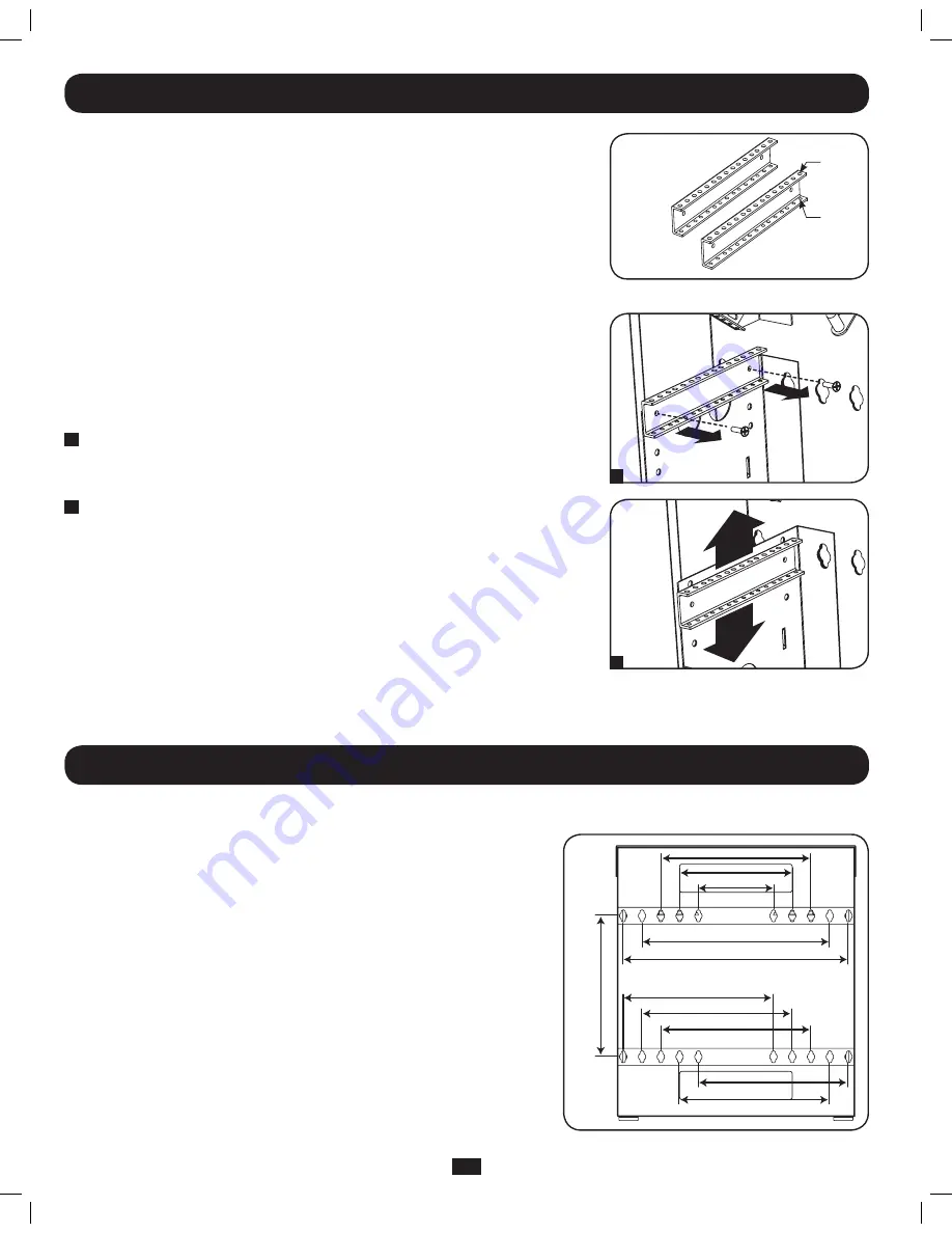
There are 20 keyhole cutouts on the back door of the enclosure arranged in 4 sets of 5. 
Each keyhole can accommodate an M10 or 3/8” bolt. The holes are on 16" centers, with 
the holes in each set 2” apart from center to center. Holes are then 15” apart vertically, 
as shown in the diagram.
Using a level, measure to position your mounting areas precisely. Use appropriate fasteners 
(not included) to secure the enclosure to the wall. 

Warning: The area you plan to mount 

the enclosure to must be able to withstand the weight of the enclosure and all 

mounted equipment. For the weight of the enclosure and its capacity, see the 

specifications on page 8.

Warning: Do not attempt to adjust rails while equipment is installed in the enclosure. Do 

not attempt to use rails without screws installed. (2 per rail.)

The two horizontal mounting rails are pre-installed to accommodate equipment with a mounting 

depth of 20 inches (508 mm). Do not adjust the mounting rails unless your equipment requires a 
different mounting depth. The rails can be adjusted in 1-inch increments for mounting depths 

between 17 inches (432 mm) and 20 inches (508 mm).

1


Each rail is connected to the enclosure with 2 screws: 1 at the front of the enclosure and one  

at the rear. Using a Philips-head screwdriver, remove the screws that fasten the rails to the 
enclosure.

2

  Slide the mounting rails vertically to the desired depth and reattach them using the screws you 

removed in Step 1.

Warning: Do not attempt to mount the enclosure to the wall with equipment mounted in the enclosure.

15”

16”

16”
12”

8”

20”
24”

16”

16”

16”

16”

1

2

M6

12-24

201107089-93-3126-EN.indd   6

8/3/2011   9:06:07 AM

Summary of Contents for SmartRack SRWF5U

Page 1: ...ting 6 7 Equipment Installation 7 8 Optional Patch Panel Installation 7 9 Specifications 7 10 Storage and Service 8 11 Warranty Warranty Registration 8 Español 9 5U Low Profile Wall Mount SmartRack Enclosure Model SRWF5U Owner s Manual W ARRANTY REGISTRATION Register online today for a chance to win a FREE Tripp Lite product www tripplite com warranty 1111 W 35th Street Chicago IL 60609 USA www tr...

Page 2: ... structurally sound area capable of handling the load or on a level floor that is able to bear the weight of the enclosure all equipment that will be installed in the enclosure and any other enclosures and or equipment that will be installed nearby Use caution when cutting packing materials The enclosure could be scratched causing damage not covered by the warranty Save all packing materials for l...

Page 3: ... Door 2 Top Panel Door 3 Horizontal Mounting Rails 4 Vertical Mounting Bracket 5 Patch Panel Mounting Bracket 6 Cable Access Holes 7 Vents 8 Wall Mounting Slots 2 7 3 5 5 6 6 6 7 7 4 1 8 8 201107089 93 3126 EN indd 3 8 3 2011 9 06 05 AM ...

Page 4: ...tore the enclosure for an extended period before installation follow the instructions in the Storage and Service section You need several tools Level Phillips head Screwdriver Appropriate tools for wall mounting You also need the following hardware Appropriate hardware for wall mounting not included Use at least two people to unpack the enclosure Never extend more than one component from the enclo...

Page 5: ...pth depending on your equipment configuration 5 3 Reversing the Front Door In order to accommodate various rack installations the front door can be reversed by switching the configuration of its latch lock and hinges To reverse the door simply remove the screws that secure the latch lock and hinges to the enclosure Move each piece to the opposite side of the enclosure so that there are two hinges ...

Page 6: ...ition your mounting areas precisely Use appropriate fasteners not included to secure the enclosure to the wall Warning The area you plan to mount the enclosure to must be able to withstand the weight of the enclosure and all mounted equipment For the weight of the enclosure and its capacity see the specifications on page 8 Warning Do not attempt to adjust rails while equipment is installed in the ...

Page 7: ...le and the holes directly above and below WARNING Follow the instructions in your equipment documentation to ensure proper installation of your equipment 1 Locate the numbered openings in the mounting rails where you plan to install your equipment Lower your equipment into the enclosure and set it down on the mounting rails lining up the mounting holes on the equipment with the mounting rail s mou...

Page 8: ... Tripp Lite has a policy of continuous improvement Specifications are subject to change without notice 10 Storage and Service 11 Warranty and Warranty Registration Storage The enclosure should be stored in a controlled indoor environment away from moisture temperature extremes flammable liquids and gasses conductive contaminants dust and direct sunlight Store the enclosure in its original shipping...

Reviews: