2
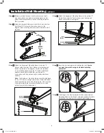
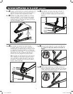
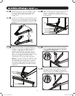
Installation/Wall-Mounting
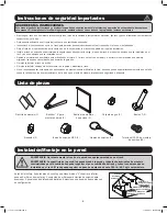
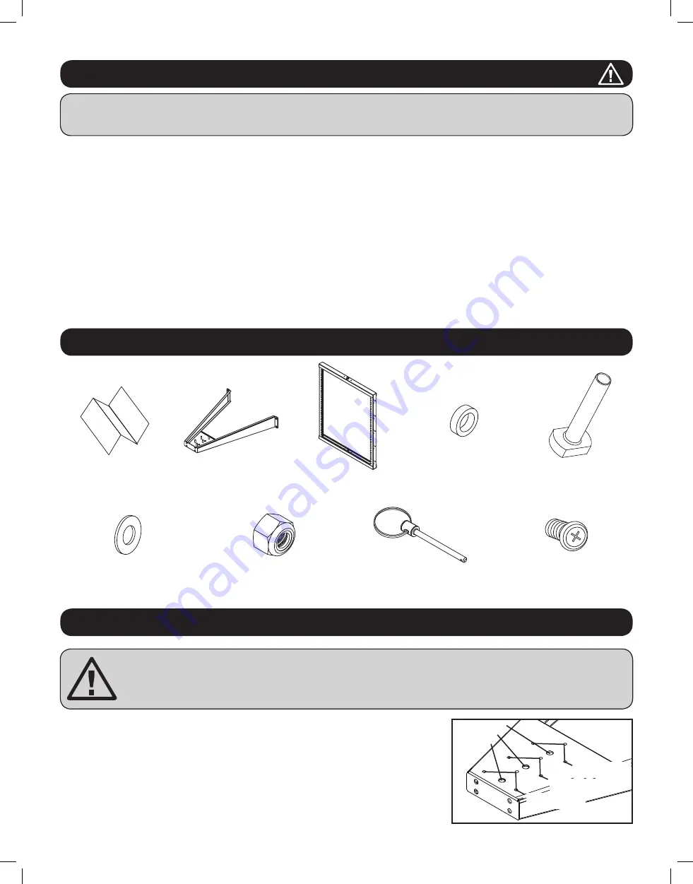
Parts List
SAVE THESE INSTRUCTIONS
This Manual contains instructions and warnings that must be followed during the installation and operation of the product described in this
manual. Failure to comply may invalidate the warranty and cause property damage or personal injury.
• Keep the rack in a controlled indoor environment, away from moisture, temperature extremes, flammable liquids and gasses, conductive
contaminants and dust.
• Leave adequate space at the front of the rack for proper ventilation.
• Inspect the shipping container and the rack for shipping damage. Do not use the rack if it is damaged.
• Leave the rack in the shipping container until it has been moved as close to the final installation location as possible.
• Install the rack in a structurally sound area capable of handling the load, the weight of the rack, all equipment that will be installed in the rack
and any other equipment that will be installed nearby.
• Save all packing materials for later use. Repacking and shipping the enclosure without the original packing materials may cause product damage
that may affect the warranty.
• Do not attempt to install the rack unassisted.
• Do not attempt to install equipment without first wall mounting and stabilizing the rack.
• Use of this equipment in life support applications where failure of this equipment can reasonably be expected to cause the failure of the life
support equipment or to significantly affect its safety or effectiveness is not recommended.
Mounting Template (1)
Wall-Mount “A” Frame (2)
Equipment Mounting
Frame (1)
Pivot Bearing (2)
T bolt (2)
Washers (4)
M10 Locknut (2)
Lock Pins (2)
#12-24 Equipment Mounting
Screws (24)
WARNING: Do not attempt to mount the rack to the wall with equipment mounted to the rack.
WARNING: The wall surface, the wall studs and all user-supplied mounting hardware must be able to support
the combined weight of the rack and all equipment that will be installed in the rack. The rack can support an
equipment load up to 150 lb. maximum.
It should be noted before mounting that both top and bottom “A” Frames have 3 mounting
holes and 3 sets of locking pin holes to accommodate 3 different mounting depth positions.
Choose a position according to your configuration.
Important Safety Instructions
Position 2
Position 3
Position 1
Position 1
Locking Pin Holes
Position 2
Locking Pin Holes
Position 3
Locking Pin Holes
17-11-211 93-2993.indb 2
11/29/2017 10:16:43 AM

