
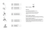

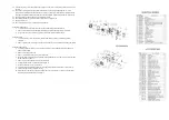
Diagram
D
Diagram
E
REPLACE CONTROL BOX
Follow pressure relief procedure before attempting to service or repair unit.
1.
If trouble shooting guide suggests replacing the control box follow the directions
below.
2.
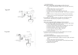
Remove 6 screws #40 and remove cover plate #70.
3.
Unthread transducer from fluid manifold #9.
4.
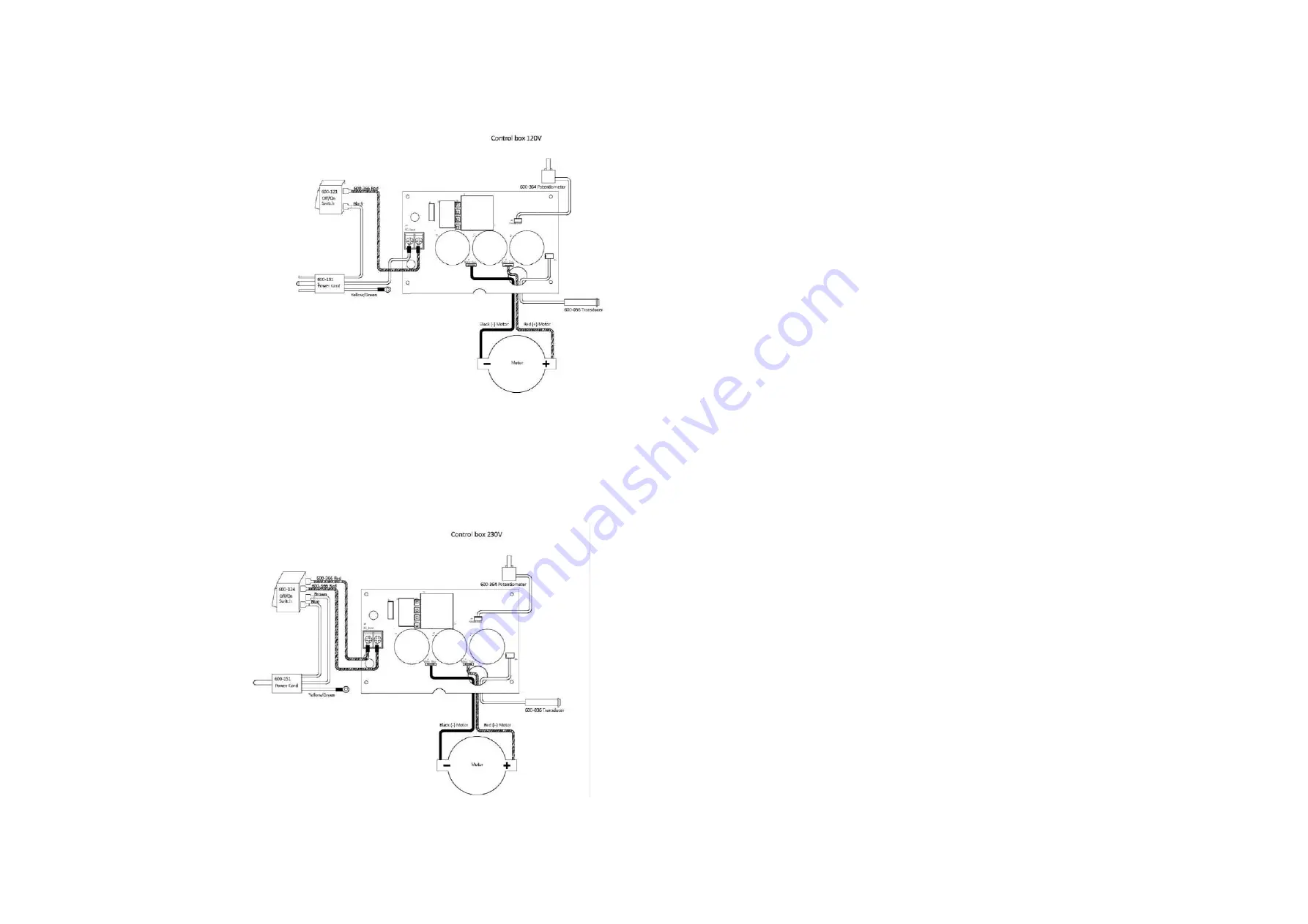
Disconnect motor leads from circuit board. See Diagram “D/E”
5.
Remove 3 mounting screws #57 from bracket #87. Unthread filter housing for easier
access.
6.
Remove control box containing circuit board, On/Off switch and potentiometer
7.
Replace in reverse order. Note: By removing motor housing will make it easier to
install control box.
Note: Although the Circuit board, tranducer, On/Off switch and potentiometer are sold
individually they are supplied together with replacement Control Box assembly.
REPLACE CIRCUIT BOARD
Follow pressure relief procedure before attempting to service or repair unit.
If trouble shooting guide suggests replacing the Circuit Board follow the directions below.
1.
Remove 6 screws #40 and remover cover plate #70.
2.
Disconnect Transducer #89 from circuit board. See diagram “D/E” and for below.
3.
Disconnect the leads from potentiometer #82 to circuit board
4.
Disconnect the leads from motor # 44 to the circuit board
5.
Disconnect lead from On/Off switch #80 to circuit board.
6.
Remove 4 screws #74 mounting Circuit Board.
7.
Replace in reverse order.
Note: Make sure to wear surgical gloves when handling circuit board. They will reduce
contaminates that may come in contact with the circuit board.
REPLACE POTENTIOMETER
Follow pressure relief procedure before attempting to service or repair unit.
If trouble shooting guide suggests replacing the potentiometer follow the directions
below.
1.
Remove 6 screws #40 and remove cover plate #70.
2.
Disconnect the leads from potentiometer # 82 to circuit board and remove knob
#85. Remove potentiometer # 82.
3.
Replace in reverse order.
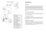
Summary of Contents for 200-517
Page 6: ......


