
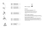


REPLACE TRANSDUCER
Follow pressure relief procedure before attempting to service or repair unit.
If trouble shooting guide suggests replacing the transducer follow the directions
below.
4.
Remove 6 screws #40 and remove cover plate #70.
5.
Unplug the wire from #89 to circuit board.
6.
Loosen housing #90 and with needle nose pyers slide traducer from filter manifold.
7.
Remove 3 screws #57. Make sure to firmly hold control box in place.
8.
Remove tranducer by guiding the wire through the circuit board and out the back of
the control box.
9.
Install new transducer by sliding the wire through grommet #91 and guiding the wire
through grommet #86 and continuing through the circuit board.
10.
Connect tranducer to the circuit board and reinstall screws #57.
11.
With needle nose pylers slider transducer into filter manifold making sure o-ring #88
stays in place.
12.
Tighten housing #90 and install cover plate #70 with 4 screws #40.
REPLACE ON/OFF SWITCH
Follow pressure relief procedure before attempting to service or repair unit.
If trouble shooting guide suggests replacing the on/off switch follow the directions below.
1.
Remove 6 screws #40 and remover cover plate #70.
2.
Disconnect the two leads from the on/off switch.
3.
Remove mounting screws #78.
4.
Remove switch indicator plate #79 and remove the on/off switch #80.
5.
Replace in reverse order.
REPLACE MOTOR BRUSHES:
Follow pressure relief procedure before attempting to service or repair unit.
If trouble shooting guide suggests replacing the motor brushes follow the directions below.
1.
Remove 3 screws #40 and remove cover #42.
2.
Use a straight blade screwdriver to remove brush retaining cap to expose motor
brushes.
3.
Remove motor brushes #48 one at a time. Inspect. Replace if worn or damaged
4.
Reassemble in reverse order. When reinstalling motor brushes make sure to have
red and black wire leads to the back of the motor housing.
REPLACE MOTOR
Follow pressure relief procedure before attempting to service or repair unit.
If trouble shooting guide suggests replacing the motor follow the directions below.
1.
Remove 3 screws #40 and remove motor cover #42.
2.
Remove 4 screws #40 and remove cover plate #70.
3.
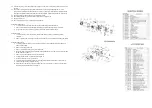
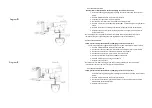
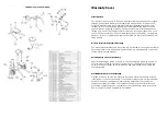
Disconnect Black and Red cap/motor leads from circuit board #73. See diagram
“D/E”
4.
Remove 4 screws #40 and remove cover plate # 55.
5.
Unthread Transducer housing # 90 and slide Transducer #89 back from Fluid
Manifold.
6.
Remove 4 screws #54 and remove crank housing and fluid manifold together.
7.
Remove crankshaft #51 and thrust washer #52.
8.
Remove reducer gear #50
9.
Remove 2 screws # 57 from underneath. Leave 2 screws #57 that attach bracket #87
to control box #92.
10.
Remove 4 screws #96 see diagram frame and siphon tubes and separate motor
complete from frame.
11.
Install reducer gear # 50 into gear box and rotate fan to insure armature shaft is
engaged.
12.
Install crankshaft and thrust washer #51, 52.
13.
Fill gear box with # 2 lithium base grease.
14.
Reconnect black and red cap/motor and transducer leads to circuit board in control
box.
15.
Complete reassemble in reverse order.
REPLACE GEARS/CONNECTING ROD
Follow pressure relief procedure before attempting to service or repair unit.
If trouble shooting guide suggests replacing the gears or connecting rod follow the
directions below.
1.
Remove 4 screws #40 and remove cover plate #55.
2.
Remove 4 screws #40 and remove cover plate #70.
3.
Remove 2 screws #25 and unthread transducer # 30 (see diagram “A”) and remove
pump/filter manifold.
4.
Remove 4 screws # 54 then remove crank housing. Connecting rod can be replaced
at this point.
5.
The reducer gear #50 and crankshaft #51 can also be replaced at this point.
6.
Complete reassemble in reverse order.
Summary of Contents for 200-517
Page 6: ......


