


• Do not operate the unit when fatigued or under the influence of alcohol or drugs
.
Stay alert and watch what you are
doing.
• Know how to stop the unit and bleed pressure quickly. Be familiar with controls.
• Do not overreach or stand on an unstable support. Keep effective footing and balance at all times
.
A PRESSURIZED ALUMINUM PARTS HAZARD
Do not use 1,1,1-trichloroethane, methylene chloride, other halogenated hydrocarbon solvents or fluids containing
such solvents in pressurized aluminum equipment. Such use can cause serious chemical
reaction and equipment rupture, and result in death, serious injury, and property damage.
TOXIC FLUID OR FUMES HAZARD
Toxic fluids or fumes can cause serious injury or death if splashed in the eyes or on skin, inhaled, or
swallowed.
• Read all MSDS’s to know the specific hazards of the fluids you are u
sing.
• Store hazardous fluid in approved containers, and dispose of it according to applicable guidelines.
PERSONAL PROTECTIVE EQUIPMENT
You must wear appropriate protective equipment when operating, servicing, or when in the operating
area of the equipment to help protect you from serious injury, including eye injury, inhalation of toxic
fumes, burns, and hearing loss. This protective equipment includes but is not limited to;
• Protective eye wear
• Clothing and respirator as recommended by the fluid
and solvent manufacturer
• Gloves
• Hearing protection
GROUNDING
:
The sprayer must be grounded. Grounding reduces the risk of static and electric shock by providing an escape wire
for the electrical current due to static build up or in the event of a short circuit.
• The sprayer power cord includes a grounding wire with an appropriate grounding contact.
• The plug must be plugged into an outlet that is properly installed and grounded in accordance with all local
codes and ordinances.
• Do not m
odify plug. If it will not fit in outlet have grounded outlet installed by a qualified electrician. Do not
use an adapter.
Use only the correct pressure rated airless hose with static ground to reduce the risk of static discharge or injection.
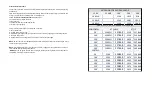
POWER REQUIREMENTS
• 110V units required 100
-120VAC 50/60Hz.
12
A, 1 phase
• 220V units require 220
-240 VAC, 50/60Hz,
6
A, 1 phase
EXTENSION CORDS
•
Use an extension cord with ground contact only. Should an extension cord be necessary use a 3 wire, 12 AWG
(2.5mm2) minimum. Do not exceed 300 ft 100 meters
PAILS
• Solvent and oil based fluids: follow local code. Use only conductive metal pails, place on a grounded surface
such as concrete.
•
Do not place pail on a nonconductive surface such as paper or cardboard which interrupt grounding continuity.
• To maintain grounding continuity when flushing or relieving pressure: hold metal part of the spray gun with the
airless tip removed firmly to side of the grounded metal pail. Then trigger gun.
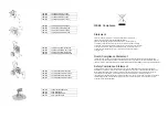
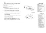
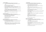
START UP
Throughout these instructions Model # T-5 and T-7 and the instructions for the T360 Airless spray gun are shown
in all illustrations.
1. Connect TriTech airless hose to sprayer. Tighten securely.
2. Connect other end of the hose to gun.
3. Tighten securely.
4. Remove tip guard.
5. Check inlet strainer for clogs and debris.
6. Fill upper retainer with TriLube to prevent premature packing wear. Do this each time you spray.
7. Plug power supply cord into a properly grounded electrical outlet.
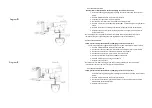
8. Turn pressure relief valve down.
9. Place siphon tube set in grounded metal container partially filled with flushing fluid. Use mineral spirits to flush
storage oil.
10. Turn pressure control to lowest pressure. Turn pressure relief valve down.
11. Turn power ON.
12. Increase pressure to start motor and allow fluid to circulate through pressure relief tube for 15 seconds; then
turn pressure down.
13. Turn pressure relief valve horizontal. Take spray gun trigger safety OFF.
14. Hold gun against grounded metal container. Trigger gun and increase fluid pressure to half way. Flush 1
minute. Inspect for leaks. If a leak occurs follow the pressure relief procedure then tighten fitting were leak
occurred. Do not attempt to stop leaks with hand or rag! Repeat Start-up 1-5 again. If no leaks, proceed.
15. Place siphon tube in paint pail.
16. Trigger gun again into metal container until paint appears. Move gun to paint pail and trigger for 20 seconds.
Set the safety to ON position. Assemble tip and guard. (See following section).
TIP AND GUARD ASSEMBLY
1. Insert metal seal and “black bellow” seal assembly by placing seals on the end of T93R Contractor tip and insert
through guard. Line up seals by turning tip.
2. Insert Tip
3. Screw assembly onto gun. Tighten.
SPRAYING
1. Spray test pattern. Start with pressure turned to its lowest setting, then gradually increase pressure until you
achieve a consistent spray pattern without heavy edges. Use smaller tip size if pressure adjustment cannot
eliminate heavy edges.
2. Hold gun perpendicular 10-12 inches in of front surface. Spray back and forth overlapping by 20%. To prevent
heavy spots, start moving the gun before pulling the trigger. When spraying, after releasing trigger continue to
move gun.
Summary of Contents for 200-517
Page 6: ......


