
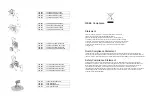

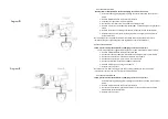
CLEARING CLOGGED TIP
a) Release trigger, put safety ON.
b) Rotate T93R Tip.
c) Take safety OFF
d) Trigger gun to clear clog. Never point gun at your hand or in a rag!
RETRUN TO SPRAY
a) Put Safety ON.
b) Return Tip to spray position.
c) Take safety OFF and continue spraying.
CLEAN UP
1. Turn power OFF and unplug sprayer.
2. Turn pressure to lowest setting. Trigger gun to relieve pressure.
3. Put pressure relief tube in pail. Turn pressure relief valve down.
4. Remove guard and T93R tip. Clean tip with soft bristle brush. DO NOT STORE IN WATER.
5. Remove siphon tube set from paint and place in flushing fluid. Use water for water base paint and mineral spirits for
oil base paint.
6. Plug in sprayer. Turn power ON. Turn Pressure relief valve horizontal.
7. Hold gun against paint pail. Take trigger safety OFF. Trigger gun and increase pressure until flushing fluid appears.
8. Move gun to flushing pail, hold gun against pail. Trigger gun to thoroughly flush system. Release trigger and put trigger
safety ON.
9. Turn pressure relief valve down and allow flushing fluid to circulate for 1 to 2 minutes to clean drain tube.
10. Raise siphon tube above flushing fluid and run sprayer for 15 to 30 seconds to drain fluid. Turn power off.
11. Close pressure relief valve. Trigger gun into flushing pail to purge fluid from hose.
12. Open pressure relief valve. Then close. Do not store with pressure relief valve open.
13. Remove filter from gun and sprayer, if installed. Clean and inspect. Reinstall filters.
14. If flushing with water, flush again with mineral spirits or TriTech Pump Cleaner to leave a protective coating to
prevent freezing or corrosion.
15. Unplug power cord from outlet and wipe sprayer, hose and gun with rag soaked in water or mineral spirits.
Pressure Relief Procedure
The sprayer’s pressure must be manually relieved to prevent sprayer from starting or spraying accidentally.
Fluid under high pressure can be injected through skin and cause serious injury. To reduce risk of injury from injection,
splashing fluid, or moving parts,
Follow the
Pressure Relief Procedure
whenever you:
• are instructed to relieve pressure
• stop spraying
• check or service any system equipment
• install or clean spray tip
PROCEDURE
1. Turn pressure control knob counterclockwise to stop.
2. Turn sprayer off.
3
.
Do not unplug power supply cord.
4. Hold metal part of gun firmly to grounded metal container. Trigger gun to relieve pressure.
5. Lock gun safety latch.
6. Open pressure relief valve. Leave pressure relief valve open until ready to spray again.
NOTE:
Do not store unit for extended periods of time with the Pressure Relief Valve open. Store the unit in the
spray position.
NOTE:
If suspected that spray tip or hose is completely clogged, or that pressure has not been fully relieved after
following steps above,
SLOWLY
loosen tip guard or hose end coupling to relieve pressure gradually, and then loosen completely. Clear
tip or hose obstruction.
ELECTRICAL SHOCK WARNING
To reduce risk of serious injury, including electric shock, do not touch moving or electrical parts with fingers or
tools while testing repair. Shut off and unplug sprayer when inspection is complete. Install all covers, guards,
gaskets, screws and washers before operating sprayer.
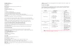
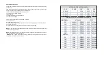
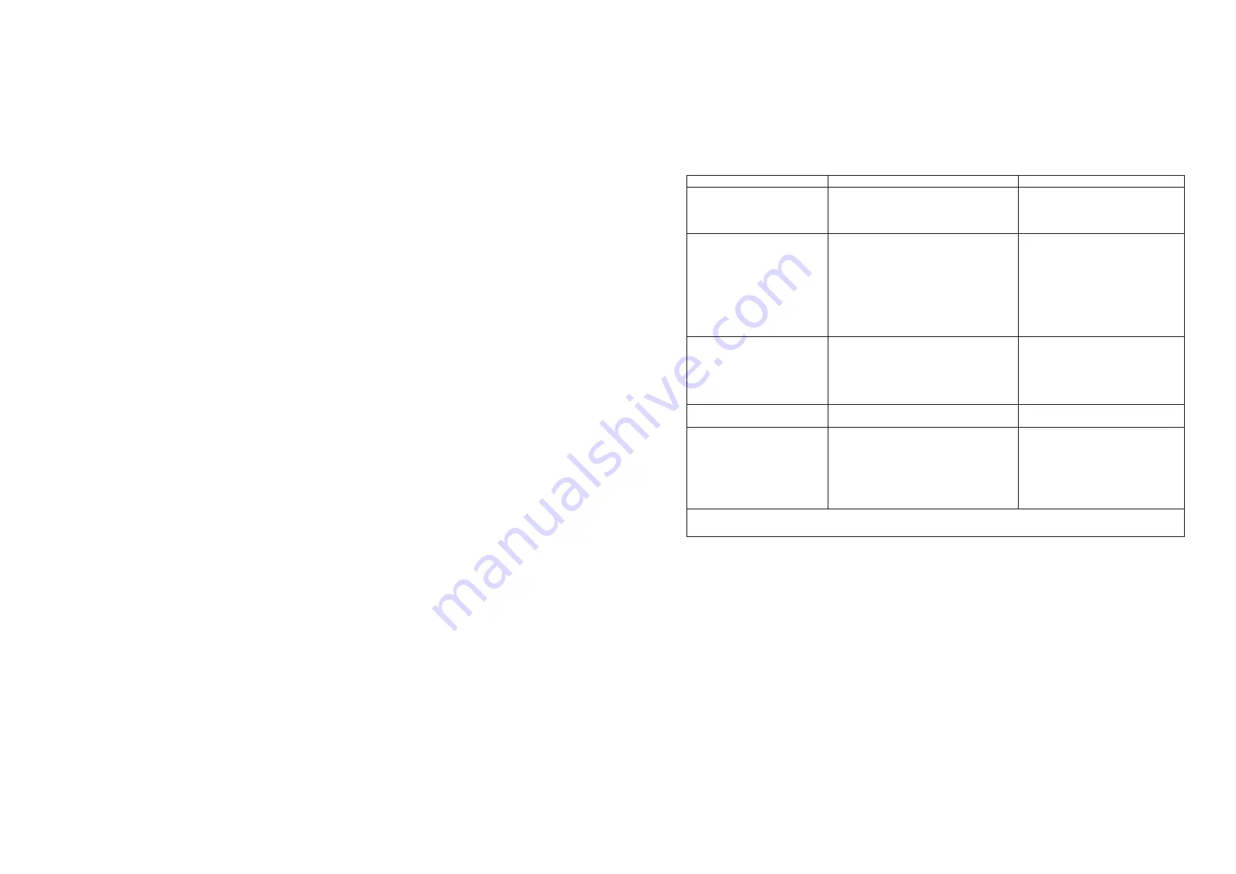
PROBLEM
WHAT TO CHECK
REMEDY
Motor will not turn on.
1.
Unit not plugged in.
2.
Pressure set too low
3.
Circuit breaker open
1.
Plug unit in.
2.
Increase pressure
3.
Check breaker and reset if
needed.
Unit will not prime
1.
Inlet tube is loose
2.
Inlet screen clogged
3.
Inlet ball stuck
4.
Outlet ball stuck
1.
Check o-ring and tighten
siphon hose
2.
Check inlet screen clean or
replace
3.
Remove siphon hose assy and
move inlet ball with pencil.
4.
Remove siphon hose and foot
valve and use pencil to move
outlet ball.
Pump builds pressure but will not
shut off
1.
Inlet ball or seat obstructed or
chipped
2.
Outlet ball or seat obstructed or
chipped
3.
Prime valve leaks.
1.
Clean or replace if needed
2.
Clean or replace if needed
3.
Replace Prime Valve if coating
leaks while under pressure.
Paint leaking front wet cup
1.
Inspect upper packing.
1.
Replace if needed
Pump output is low
1.
Spray tip worn
2.
Lower or Upper ball worn
3.
Prime valve worn
1.
Inspect tip by checking fan
pattern width. If worn replace
2.
Inspect lower and upper ball
for damage. Replace if
damaged or worn.
3.
If prime valve leaks while
spraying clean or replace.
NOTE:
Before performing any inspection or repair follow the pressure relief procedure. Never attempt to do any
service or repair while the unit is plugged in or under pressure.
Summary of Contents for 200-517
Page 6: ......


