
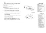
(A)
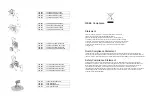
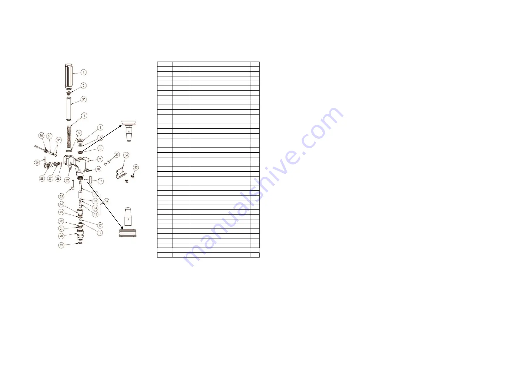
FLUID MANIFOLD
Both upper and lower packing are shown pushing off the shipping tool.
Tool is for shipping purposes only and not to be used for packing installation.
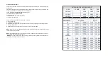
ITEM NO PART NO. DESCRIPTION
QTY
1
600-211 HOUSING, FILTER
1
2
600-255 SPRING, FILTER
1
3
600-141-05 FILTER, 50 MESH
1
4
600-240 CORE, SPRING
1
5
600-353 O-RING
1
6
600-033 RETAINER, UPPER
1
7
600-035 GUIDE,UPPER
1
8
600-017 PACKING, UPPER
1
9
600-0083-75 MANIFOLD, FLUID
1
10
120-001 FITTING, HOSE
1
11
600-024 PACKING, LOWER
1
12
600-099-75 ROD ,PISTON
1
13
600-047 BALL, UPPER
1
14
101-001 O-RING
1
15
600-118-75 VALVE, PISTON (INCL.14)
1
16
600-090-75 ROD, PISTON COMPLETE (12-15)
1
17
600-022 BALL, INTAKE
1
18
600-021 SEAT, INTAKE VALVE
1
19
600-234 WASHER
1
20
600-251 HSG, INTAKE VALVE (INCL.19-22)
1
21
600-279 O-RING
1
22
600-353 O-RING
1
23
600-367 O-RING
1
24
600-249 GUIDE, PISTON (INCL.23)
1
25
600-199 BOLT
2
26
600-166 O-RING
1
27
600-157 VALVE, PRESSURE RELIEF (INCL.26)
1
28
600-437 HANDLE & CAM (INCL.29)
1
29
600-214 PIN, PRESSURE RELIEF
1
30
600-030 HSG, TRANSDUCER
1
31
600-456 TRANSDUCER (INCL.30-31,36)
1
32
600-208 FITTING, HOSE, BARB MALE
1
33
600-242 PLUG, BRACKET MOUNT
2
34
600-320 HOOK, PAIL (HI CART ONLY)
1
35
600-541 SCREW (HI CART ONLY)
2
36
600-418 O-RING
2
600-455 KIT, REPACKING(INCL.7,8.11,13,14,17,21-23) 1
600-335 FLUID MANIFOLD COMPLETE (1-24, 26-32) 1
3
600-141-10 100 MESH FILTER
1
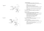
PAINT/FILTER MANIFOLD SERVICE AND REPAIR
REPACKING PAINT/FILTER MANIFOLD
Follow pressure relief procedure before attempting to service or repair unit.
1.
Remove suction set by unthreading nut item # 85, see frame and siphon tube then pull downwards the
inlet adaptor from intake housing # 20. Remove return hose #90 from pump/filter manifold. Remove
suction set from unit.
2.
Remove filter bowl #1 and filter and spring support #3 and 4. Inspect and clean or replace filter screen #3.
3.
Remove intake valve housing #20.
4.
Remove Piston guide #24 by inserting a ¼” slotted screwdriver in the gap between the upper side of the
intake valve housing and the piston guide. Gently pry upwards until piston guide is free from intake valve
housing.
5.
Carefully inspect ball #17 and seat #18. If worn replace. Note seat #18 can be flipped over to the other
side if worn or damaged. If repacking the unit is necessary always make sure to replace ball #17 and
gaskets 22 and 21.
6.
Insert ¼ Hex key into piston valve assembly # 16 and turn counter clockwise to remove piston valve # 15.
Inspect upper ball #13 and carbide seat of piston valve #15. Replace if worn or damaged. Make sure to
always replace upper ball #13 and o-ring #14 if repacking unit.
7.
To remove the pump/filter manifold housing use a 5/16” Hex wrench in the 2 mounting bolts #25. Then
unthread transducer #30 from the back of paint/filter manifold.
8.
Remove crank housing cover plate # 55 diagram “B”.
9.
Insert a slotted screwdriver between crank housing # 53, see diagram “B” and fluid manifold # 9 gently
pry downwards until a gap can be seen between # 9 and #53. Then slide pump/filter manifold # 9 from
unit.
10.
Using a 1” open end or adjustable wrench to remove upper retainer #6.
11.
Remove piston rod # 12 by pushing downward with your hand.
12.
Inspect upper and lower packings #8 and #11 in place. Do not remove packings to inspect. Remove only if
you intend to replace them.
13.
When replacing packings make sure to fill the inside of the packings with “packing grease” supplied in
repair kit 600-455. Also apply grease on o-ring on the outside of the packing to make insertion easier.
14.
Remove upper packing from shipping tool. Insert upper packing in to the top of pump/filter manifold #9.
Packing can only go in one direction.
15.
Remove lower packing from shipping tool. Insert lower packing #11 in the bottom of the pump/filter
manifold. Packing can only go in one direction.
16.
Thread upper retainer #6 after replacing upper guide #7. Leave hand tight until piston is installed.
17.
Insert upper ball #13 into piston #12 while holding piston upside down.
18.
Thread piston valve #15 into piston. Make sure to replace o-ring #14.
19.
Using connecting rod item #56 (see diagram “B”) to hold piston use a ¼” hex wrench to tighten piston
valve firmly into piston.
20.
Replace o-rings #23, 22 and 21 below seat in intake valve and on Piston Guide. Insert lower ball and seat
#’s 17 and 18 and firmly push piston guide into intake valve housing #20.
21.
Slide piston # 12 into intake valve housing assembly. Insert piston through lower packing until it stops.
Then thread intake valve assembly into pump/filter manifold. The intake valve housing assembly will push
piston through packings correctly. Once intake valve housing is threaded all the way use needle nose
pliers on the slots of the top of the piston to align slots front to back.
22.
Using a 1” open end wrench or adjustable wrench tighten upper retainer # 6 firmly.
Summary of Contents for 200-517
Page 6: ......