Installation
Intelligent Gyro Compass (iGC)
0707-SOM-00004-7
17
© Tritech International Ltd.
Mode
Jumper JP1
Jumper JP2
Jumper JP3
RS232 only
(don't care)
(don't care)
(don't care)
RS485
(end
terminated)
Position 2-3
Position 2-3
IN
RS485
(unterminated)
Position 2-3
Position 2-3
OUT
Note
Depending on the manufacturing date of the iGC, the unit may not have a tri-
jumper assembly. In this instance the presence of the jumpers JP1 and JP2 is
only required when using RS485 communications.
4.4.2. Adjusting iGC Mode or Jumpers
In order to adjust the Mode switch settings the iGC must be opened. Firstly isolate the iGC
supply and disconnect the iGC from its interconnecting cable (if already connected).
Follow the procedure for iGC Disassembly (see Section 8.7, “ Dismantling and Re-assembly
”). This procedure exposes the internal iGC components.
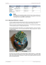
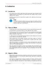
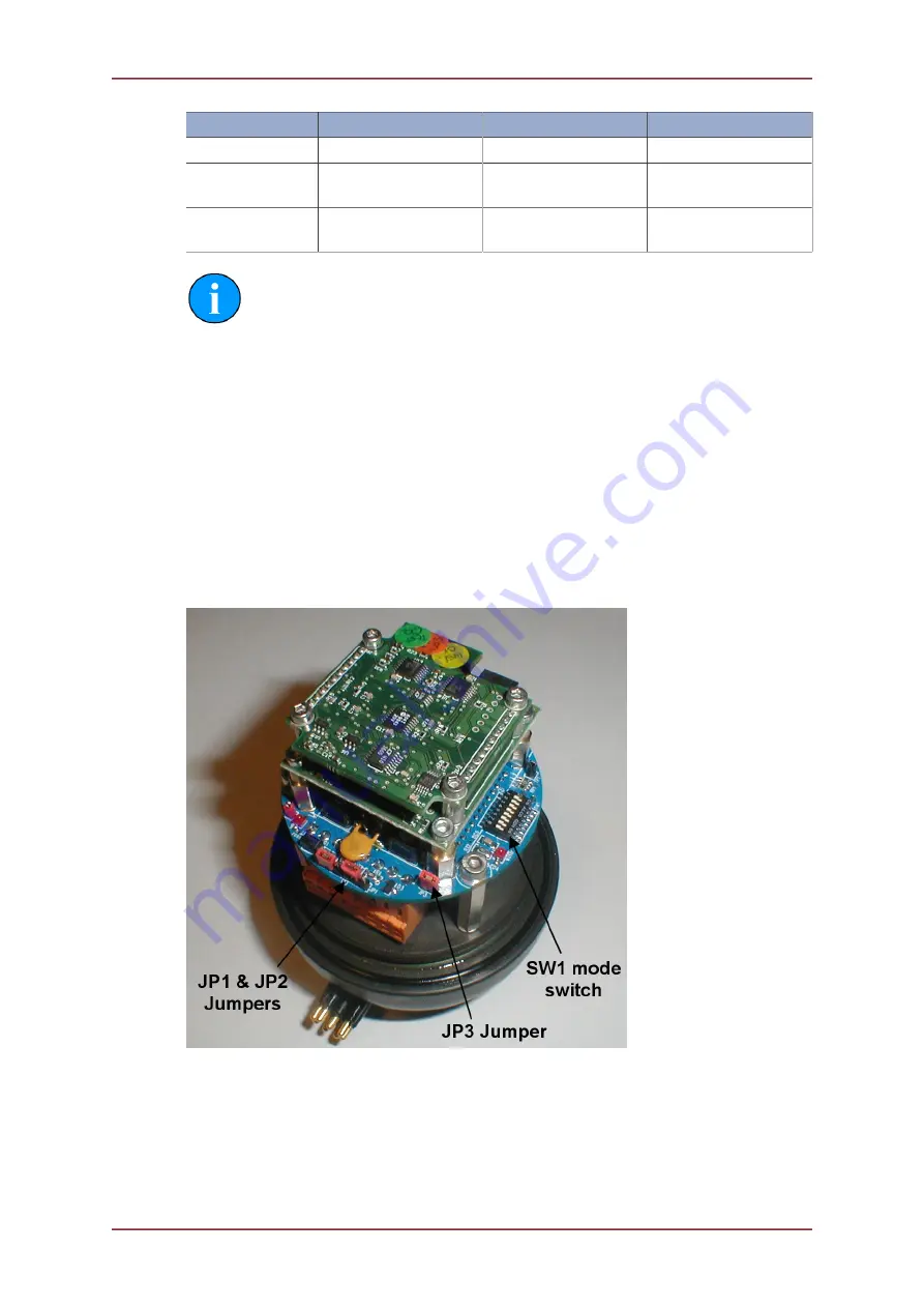
Identify the Mode Selector switch (SW1) on the Interface PCB (Item 4 on the G.A.). Refer
to the photograph below, and to the General Assembly drawing in Appendix B,
.
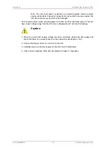
Set the DIL mode switch (SW1) to the desired setting (as determined above – and according
to the switch settings from Appendices C and D). Operate the switches carefully with a sliding
motion using a small jeweller’s screwdriver or similar, ensuring that the switches are moved
fully into the desired position.

