Maintenance
Intelligent Gyro Compass (iGC)
0707-SOM-00004-7
33
© Tritech International Ltd.
In all cases it is recommended that the unit be returned to Tritech for repair / test and pressure
testing prior to returning to service.
8.7. Dismantling and Re-assembly
Before starting to dismantle the iGC:
1. Refer to Section 4.2 - Safety Notes at the beginning of this manual.
2. All relevant parts of this section of the manual should be read and understood
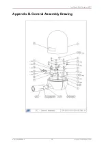
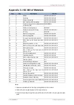
3. Refer to the Appendices for details of exploded views and identification of components
4. Ensure that power to the iGC has been turned off, the connector disconnected and the
iGC removed to a suitable workshop environment
The main components inside the iGC include:
1. Sensor Assembly (Item 3), which consists of the top two boards
2. Interface PCB Assembly (Item 4) – the blue circular PCB
3. Processor module (Item 24) – the small PCB underneath the interface PCB
4. Underwater connector tails and orange interface connector (Item 11)
The Sensor Assembly, Interface PCB and Processor module should be regarded as a single
replaceable unit.
8.7.1. Removal of Pressure Dome
The procedure for removal of the dome is as follows:
1. Thoroughly clean and de-grease the outside of the iGC
2. Unscrew the dome (Item 1) from the end cap (Item 2). Normally this can be done by hand
with the assistance of clean rubber gloves (or rubber sheet) to improve grip on the smooth
anodised surface. If additional torque is required a pair of strap wrenches can be used,
or fasteners can be inserted into the end cap to allow it to be held in a vice and a strap
wrench then used to unscrew the dome.
In all cases care must be taken to avoid damaging the anodising.
8.7.2. Removal Of Sensor Assembly, Interface PCB and Processor Module
The procedure for removal of the Sensor Assembly, Interface PCB and Processor Module
(as a single unit) is as follows:
1. Remove the dome (Item 1)
2. Unscrew the two cross head screws (Item 16) that attach the two regulators to the heatsink
block projecting from the end cap base. Remove the washers (Item 13), small plastic
insulating bushes (Item17) and the flat insulating washer (Item18) and store carefully
3. Unscrew the three M3 socket head cap screws (Item 12) that attach the Interface PCB
(Item 4) to the three hexagonal spacers (Item 10)

