Installing the System
MicronNav System
0656-SOM-00001-07
28
© Tritech International Ltd.
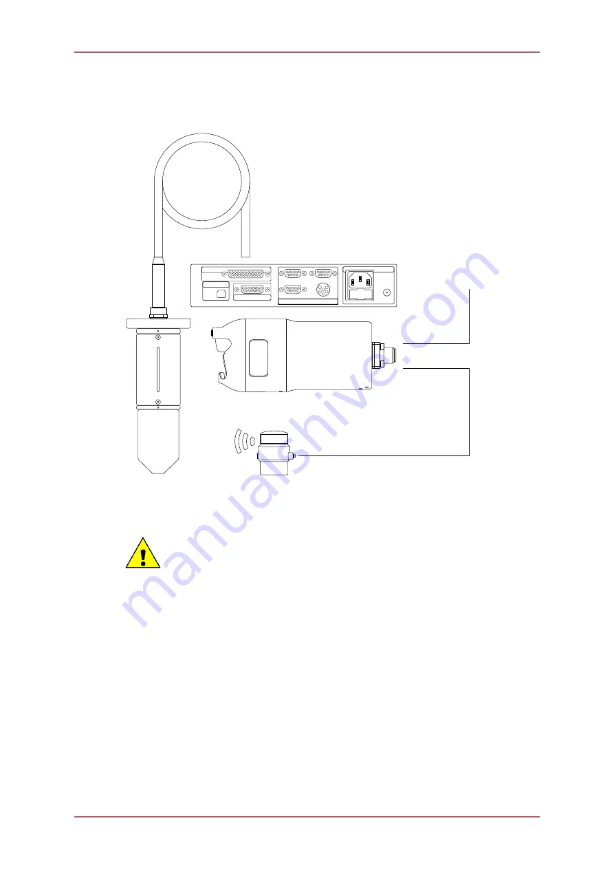
Connecting to a MicronNav Responder from a Gemini AUX Port
An example of a Micron Responder being used on the AUX Port of a Gemini is:
MICRON RESPONDER
4 5
1 2
8
6
3
7
9
4
5
1
2
8
10
6
3
7
12
9
11
14 13
15
4 5
1 2
8
6
3
7
9
4
1
3
2
6
5
AIF (ARCNET)
COMMUNICATION PORTS
PC-USB
SUPPLY
A
B
D
C
4 5
1 2
8
6
3
7
9
4
5
1
2
8
15
6
3
7
17
14
16
19 18
20
11
12
9
22
13
10
24
21
23
25
TRANSDUCER
MICRONNAV HUB (REAR)
AUX SERIAL PORT:
CONNECTED TO MAIN PORT
OF MICRON RESPONDER
MAIN PORT:
CONNECTED TO AUX PORT
OF GEMINI 720is
MAIN ETHERNET PORT:
CONNECTED TO ETHERNET
INFRASTRUCTURE (MUX POD ETC)
GEMINI 720is
USBL DUNKING TRANSDUCER
DUNKING TRANSDUCER FITTED TO
25 WAY CONNECTOR ON MICRONNAV HUB
The MicronNav Responder can be connected to the
AUX Port
of a Gemini unit (720i, 720id
or 720is) so long as the Gemini unit is identified as being Node 100.
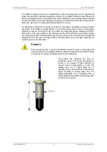
Caution
When utilising the
AUX Port
of a Gemini Sonar, care should be taken to ensure
that the power supplied to the unit does not exceed the rating of the Responder
unit. Gemini 720i / 720id units do not regulate the
AUX Port
voltage so the
Sonar itself should never be supplied with more than 48V. The Gemini 720is
does
regulate its
AUX Port
voltage to 24V.
The
AUX Port
of the Gemini should be setup to match the MicronNav Responder
communications (
RS232, 9600 Baud, 8 Data bits, 1 Stop Bit, No Parity
). Please refer to the
relevant Gemini Product Manual for detailed instructions on this process.
3.2.5. Subsea Hardware Transponder Configuration
Install the MicronNav sub-sea Modem Head as detailed in Section 3.1.2, “Mounting the
Subsea Modem Head” and, checking the connector threads are clean and contacts dry,
carefully connect the previously wired 6-pin Micron Connector Pigtail lead to the “Main”
connector port of the Modem Head.
Ensure the blanking cap on the “Aux” port of the Modem Head is fitted.

