Operation
MicronNav System
0656-SOM-00001-07
80
© Tritech International Ltd.
PPI Cursor (Position Readout)
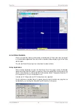
The position of the cursor on the PPI display can be made available by selecting the
paintbrush at the top of the PPI display followed by PPI Cursor from the sub-menu.
PPI Display (Settings)
The user has available several options for the PPI display format - these options are accessed
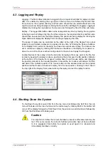
by selecting the paintbrush at the top of the PPI display followed by PPI Display from the
sub-menu.
As can be seen from the captions the user can choose to display Ship Snail Trail, Sub Snail
Trail, Circular rings, Range Cross, Range Labels and Grid. (In this context “Sub” refers to the
tracked object or ROV) The snail trail length can be adjusted here and also the number of
rings. It is suggested the user experiments with these controls to select a suitable display.
Ships Head Up / North Up
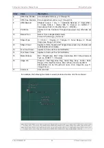
For the application of the Heading data, the PPI display can be oriented with North Up or
Ships Head Up. Click on one of the menu items to select that option. Only of these options
can be selected at a time, indicated by the ( ).
Show Ship Outline
Tick this menu item to select to display a ship outline on PPI Display.
PPI Markers
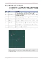
To enable measurements to be taken on the PPI display the PPI Marker feature has been
provided, to use this feature select the paintbrush at the top of the PPI display followed by PPI
Markers from the sub-menu. Four pairs of markers are provided ‘A-B’, ‘C-D’, ‘E-F’ and ‘G-
H’, each pair can be dropped on to the PPI display and provide range and bearing between
each end of the pair. Select one of the pairs from the sub-menu (i.e. A-B) to open the Markers
display panel, position the cursor over the first marker and left click to drop onto the display,
then position the cursor over the marker, hold down the left mouse button, drag the marker
to the required position and release the left mouse button to confirm its position. Repeat this


