

Operation
SeaKing & SeaPrince Imaging Sonars
0374-SOM-00001, Issue: 08
26
© Tritech International Ltd.
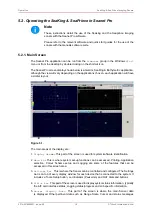
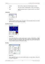
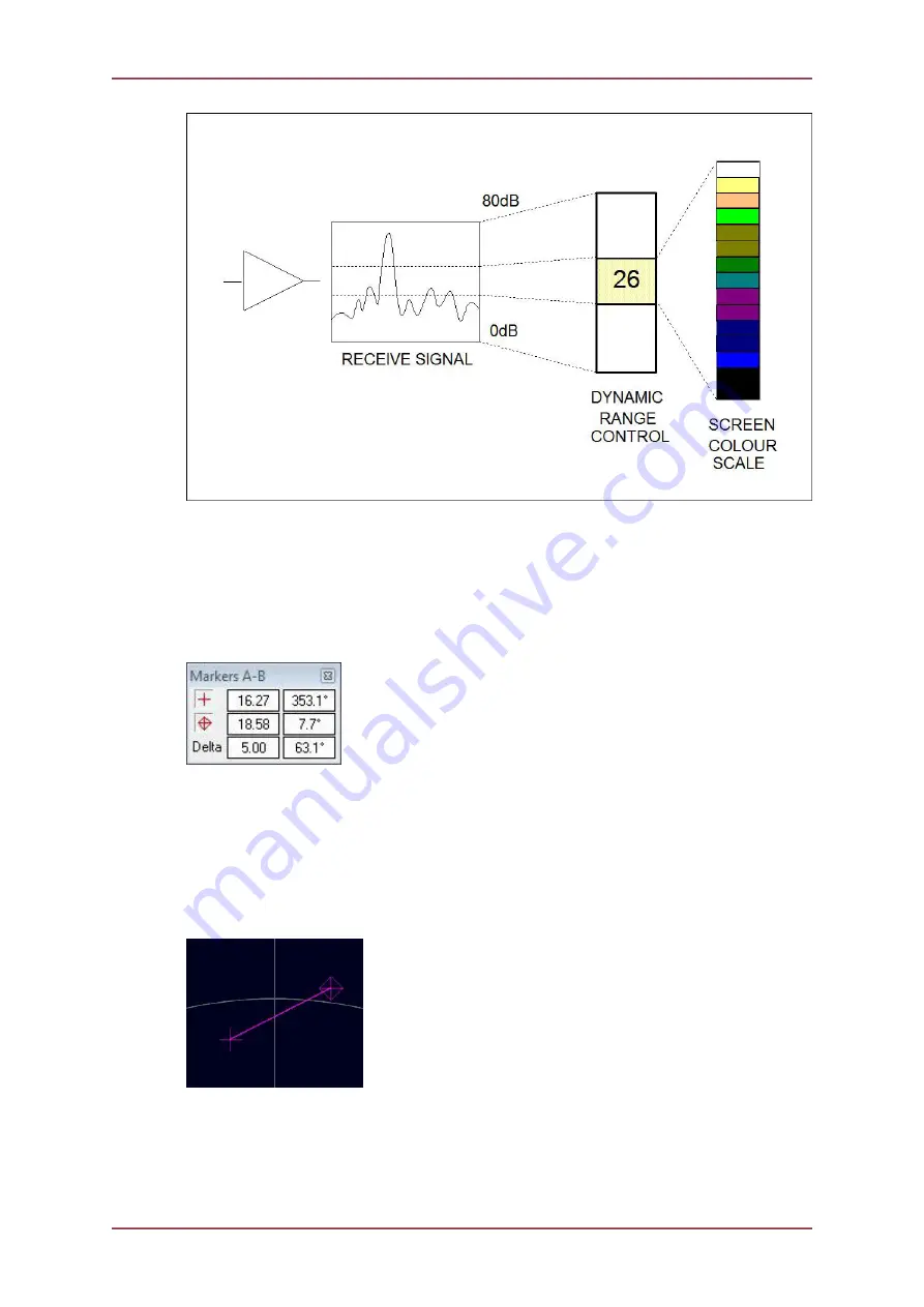
Figure 5.15.
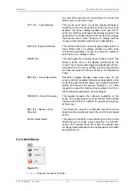
5.2.6. Application Tools
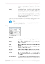
Markers
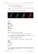
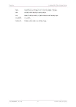
Figure 5.16.
Adds A and B markers onto the sonar display, the range and bearing to each marker &
separation and relative bearing are shown.
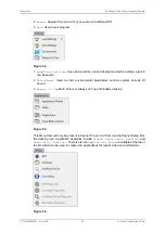
Click on the symbol to deploy on the
Marker
panel and that marker symbol will be dropped
at the Origin (0, 0) on the Sonar display. Then, pick up the Marker using the left mouse button
and drag it to the position required.
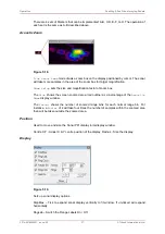
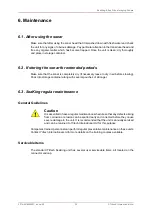
Figure 5.17.
When both markers are dropped on the display, a line will be drawn which connects them.
The ‘Delta’ Range and Bearing at the bottom of the panel indicates separation and angle
between both Markers.


