Installation Instructions
FOR OFFICE FURNITURE, STORAGE CABINETS, LOCKERS, SAFES, VAULTS, SECURED ENCLOSURES
CORE REPLACEMENT LOCK
1
R
O
R
O
TriTeq Lock and Security
701 Gullo Ave
Elk Grove Village, IL 60007
Phone: (847) 640-7002
Toll Free: (888) 603-5625
Email: marketing@triteqlock.com
www.microiqlock.com
Steelcase
© Copyright 2014 TriTeq Lock and Security. All rights reserved
062415 - Rev. 6
TM
.39
1.00
3.86
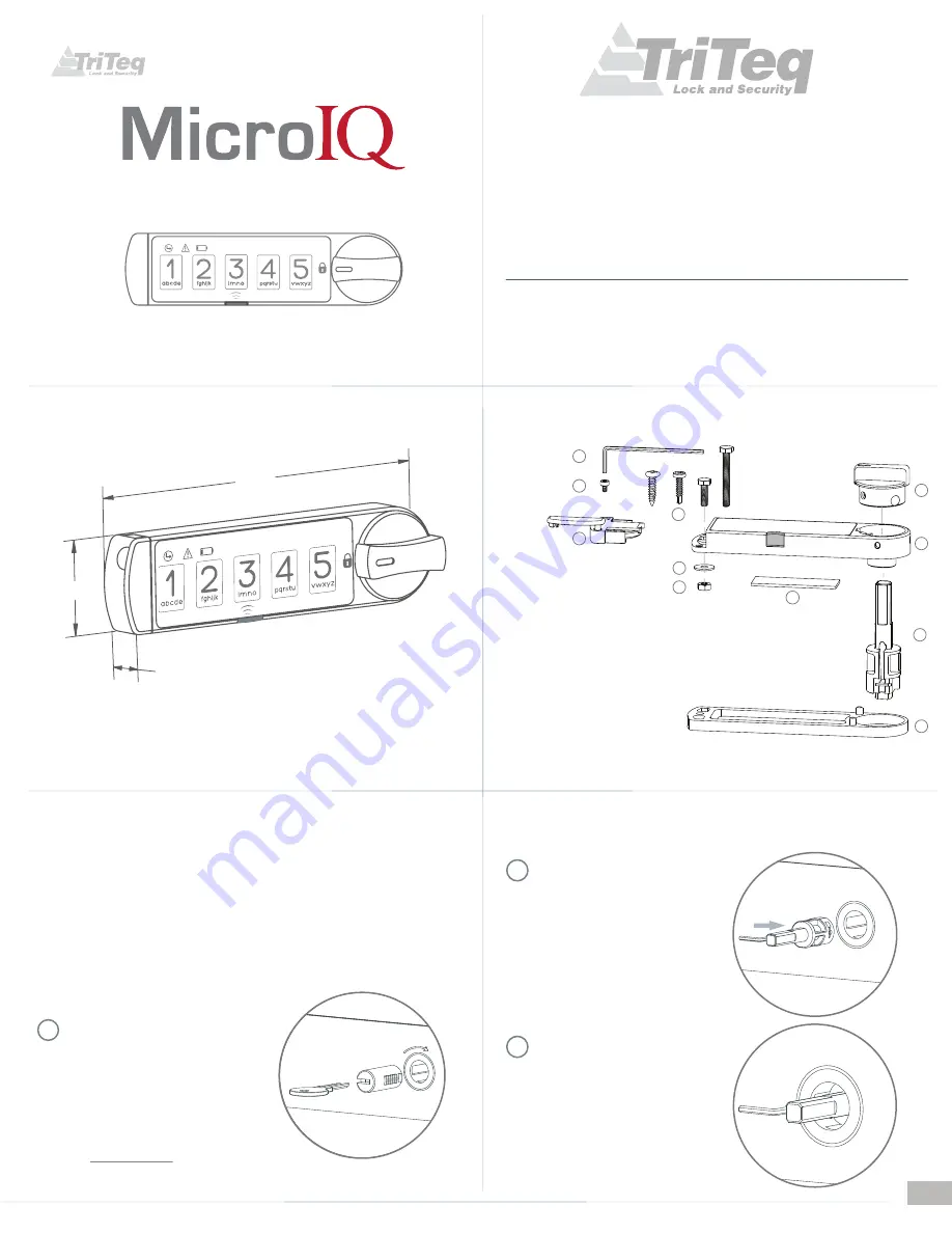
General dimensions
Fig. 1
11
Mounting screws
( select one )
3M - VHB 4952 Foam tape
( optional )
Lock Housing with keypad
and infrared receiver
CR2032 - 3 Volt Lithium Battery and battery holder
1
2
3
4
5
6
7
8
9
10
11
Spindle
Knob
Mounting nut
Mounting washer
Hex tool (1.5 mm)
Temper proof battery holder screw
1
9
10
4
2
3
5
6
7
8
0.1” or 0.187” Spacers ( optional )
#4
#4
M3
M3
M2
See
Figure 1
for available mounting hardware for the
Micro
IQ
. When mounting the
Micro
IQ
to a
cabinet door or drawer, the existing handle should be used to operate, open and close the door
or drawer.
Installation
Additional mounting fasteners
( item 10 )
are provided and must be added through the battery
extremity of the housing. Select the fasteners that best fit your panel material and thickness.
If drilling is required for thick panels use the drilling template provided at the end of this
manual. Double sided tape is also provided.
Using your change key, turn the lock to
the extreme CW position and remove the
lock core.
Note the position of the retaining
tumbler on the lock core removed
i.e.: 12 o`clock, 3, 6 or 9 o`clock position.
Example:
3 o`clock position
1
Rotate CW
You can purchase the change key online
at:
www.easykeys.com
Push the hex tool into the spindle
slot and move the tool toward the
spindle shaft until the upper edge
of the retaining tumbler is retracted.
Insert the spindle with the retaining
tumbler at the same orientation as
the lock core that was removed,
such as 3 o’clock in this example.
2
While holding the spindle in,
remove the hex tool.
Confirm that the spindle is
engaged into the lock shell.
3


