background image


            -

        - 


XM340-V1.2 - A 

26 


CLEANING AND MAINTENANCE 

We recommend a frequent cleaning of the device. Please use a soft lint-free and 
moistened cloth. Never use alcohol or solvents!   


There are no servicable parts inside the device. Maintenance and service operations 
are only to be carried out by authorized dealers.   
Should you need any spare parts, please use genuine parts. 


If the power supply cable of this device becomes damaged, it has to be replaced by 
authorized dealers only in order to avoid hazards.   
Should you have further questions, please contact your dealer. 

INSTALLATION 

This device is only constructed for a standing installation. The device must only be 
installed absolutely planar at a vibration-free, oscilation-free and fire-resistant 
location. Make sure that the device is installed absolutely planar by using a 
water-level. 
 

TECHNICAL SPECIFICATIONS 

Power supply

:

 AC 100V-240V~

50 Hz / 60Hz     

Power consumption

:

 max. 80 W 

Packing dimensions

:

 40 x 30 x 48 CM 

Net weight

:

 7 KGS   

Gross weight:

 10KGS   


Remark

:

 errors and omissions for every information given in this manual except. All information 

is subject to change without prior notice. 


Summary of Contents for WALLY LPAR21

Page 1: ...PROFESSIONAL MOVING HEAD USER MANUAL WALLY LPAR21 KEEP THIS MANUAL FOR FUTURE NEEDS...

Page 2: ...his manual consider this manual to be part of the total product keep this manual for the entire service life of the product pass this manual on to every further owner or user of the product download t...

Page 3: ...e 100 000 hr and lower power consumption 3 DMX channel modes 3 4 7 channels 3 operational modes DMX 512 Master Slave Sound Active Switch mode power supply Automatic power supply adaption between 100 a...

Page 4: ...XM340 V1 2 A 3 Overview 1 Housing 2 LEDS 3 Floor stand 4 Menu button 5 Up button 6 Down button 7 Enter button 8 Power input 9 DMX output 10 DMX input...

Page 5: ...o environmental changes do not switch it on immediately The arising condensation could damage the device Leave the device switched off until it has reached room temperature This device falls under pro...

Page 6: ...ances keep more than 50cm distance with wall for smooth air flow so there should be no shelter for fans and ventilation for heat radiation If the external flexible cable or cord of this luminaire is d...

Page 7: ...e device is not exposed to extreme heat moisture or dust The minimum distance between light output from the projector and the illuminated surface must be more than 0 1 meter Operate the device only af...

Page 8: ...weight for 1 hour without any harming deformation The installation must always be secured with a secondary safety attachment e g an appropriate safety rope Never stand directly below the device when...

Page 9: ...load limits installation material being used and periodic safety inspection of all installation material and the device If you lack these qualifications do not attempt the installation yourself Improp...

Page 10: ...ion spot Insert the end in the carabine and tighten the safety screw DMX 512 control connection Connect the provided XLR cable to the female 3 pin XLR output of your controller and the other side to t...

Page 11: ...n a discotheque it is recommended to use a DMX terminator This helps in preventing corruption of the digital control signal by electrical noise The DMX terminator is simply an XLR plug with a 120 resi...

Page 12: ...Shut off LED display 1 SET MIC M XX M 70 Mic sensitivity CHAN 3CH 4CH 7CH Set channel mode AUTO Clos Hold Auto Audi No DMX Status FANS HIGH AUTO Fan s mode select LODA ON OFF Restore factory settings...

Page 13: ...N or DISP by pressing UP or DOWN button 3 Press ENTER for selecting the desired sub menu DMX address setting Slave setting DMX address setting With this function you can adjust the desired DMX address...

Page 14: ...an adjust the desired DMX address via an external controller This function can only be activated when the DMX value of all other channels is set to 0 on the controller Select EBOC by pressing UP or DO...

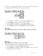
Page 15: ...on menu 3 Select ALON or MAST by pressing UP or DOWN button 4 Press ENTER to confirm or Press MENU to return to the main menu Display the DMX value Reverse display Shut off LED display Display the DMX...

Page 16: ...pressing UP or DOWN button 2 Press ENTER the display shows ON or OFF 3 Press UP to select ON if you wish to enable this function or press DOWN button to OFF if you don t the display will rotate by 180...

Page 17: ...XX XX stands for the number from 0 to 99 3 Press ENTER to confirm or Press MENU to return to the main menu Set channel mode With this function you can set channel mode 1 Select CHAN by pressing UP or...

Page 18: ...confirm or Press MENU to return to the main menu Restore factory settings With this function you can restore the factory settings of the device All settings will be set back to the default values sha...

Page 19: ...UP or DOWN button to select ADJU Test function of each channel With this function you can test each channel on its correct function 1 Select TEST by pressing UP button 2 Press ENTER the display shows...

Page 20: ...n menu Lamp running time With this function you can display the running time of the lamp 1 Select LATI by pressing UP button 2 Press ENTER the display shows XXXX X stands for the number of hours 3 Pre...

Page 21: ...essing UP or DOWN button 2 Press ENTER the display shows S XX X stands for the total amount of steps you want to save so you can call up to 48 scenes in RUN For example if the XX is 05 it means that R...

Page 22: ...the scene SC01 SC48 the before 16 scenes are defaulted to the presupposed scenes the specific colors as follows Order Color Red cost Blue cost Green cost 1 Red 255 0 0 2 Green 0 255 0 3 Blue 0 0 255...

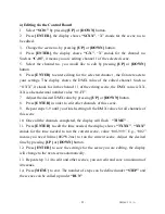
Page 23: ...decimal number value 01 FF 7 Adjust the desired DMX value by pressing UP or DOWN button 8 Press ENTER in order to edit other channels of this scene 9 Repeat steps 5 9 until you finish setting all the...

Page 24: ...OWN button 5 Press ENTER the display shows OFF 6 Press UP or DOWN button the display shows ON 7 Press ENTER the display shows SC02 You successfully downloaded the first scene 8 Adjust the Step time as...

Page 25: ...d 0 255 Red 0 Black 255 100 Red 2 2 3 Green 0 255 Green 0 Black 255 100 Green 3 3 4 Blue 0 255 Blue 0 Black 255 100 Blue NA NA 5 Shutter strobe 0 31 Led trun off 32 63 Led turn on 64 95 Strobe effect...

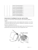
Page 26: ...door and frost filter For this device the barn door and the frost filter can be installed separately or together 1 When only install the frost filter use the rotating clips on the lens cover to fix i...

Page 27: ...only in order to avoid hazards Should you have further questions please contact your dealer INSTALLATION This device is only constructed for a standing installation The device must only be installed a...

Reviews: