7
Note
: To determine the sanding mode the sander is currently set to, disconnect the tool from the power supply, and attempt to turn the Hook and Loop Backing Pad
(2) by hand. If the pad is hard to turn and moves on an eccentric orbit, Forced rotation mode is selected. If the base turns easily around its axis, the sander is set to
Free-run mode.
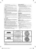
Anticlockwise (left) switch position
Free-run mode
Fine sanding with low material removal
This operating mode is recommended for handling
sensitive surfaces as well as for fine polishing.
As a result of the free running backing pad,
an application pressure dependent rotational
movement at constant eccentric motion is
achieved. By varying the application pressure, the
material removal can be regulated slightly.
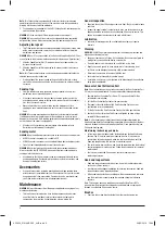
Clockwise (right) switch position
Forced rotation mode
Coarse sanding with high material removal
& buffing
This operating mode achieves highest material
removal and is recommended for working very
rough, insensitive surfaces. This mode is also
recommended for buffing. As a result of the forced
rotation, the backing pad constantly moves on an
eccentric orbit, whilst rotational around its axis.
Hook and Loop Backing Pad (2)
2. Remove any dust or debris from the Hook and Loop Backing Pad
3. Match the holes in a suitable disc with the holes in the Hook and Loop
Backing Pad
4. Simply press the disc on to the pad to attach it
Note
: To maximise the life of the hook and loop base, peel the sanding disc
off slowly rather than rapidly removing it to avoid damage to the hook and
loop system.
WARNING
: Take care to regularly clean out the build-up of dust on the base
underneath the sanding disc and not to let the disc wear completely down
before replacing it. Failure to observe these two precautionary measures can
lead to damage to the hooks and loops on the base, and the sanding disc will
not attach properly.
Adjusting the auxiliary handle
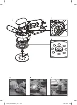
• Height and position of the Auxiliary Handle (5) can be adjusted to adapt the
tool to different work positions and to match user preference (image A):
1. Loosen the handle clamping mechanism by lifting the Auxiliary Handle
Adjustment Lever (4)
2. Adjust the handle height as required, and rotate the handle to the desired
position
3. Tighten the Auxiliary Handle Adjustment Lever to lock the Auxiliary Handle
in its new position
Dust extraction
Note
: This sander is designed to be connected to a household vacuum cleaner
hose or workshop dust extraction system. This is the preferred and most
effective method of dust extraction.
WARNING
: Always ensure that the tool is switched off and disconnected from
the power supply before attaching or removing any accessories.
WARNING
: Always connect the sander to a suitable vacuum cleaner or
workshop dust extraction system if the sanding dust contains harmful
substances, such as particles from old paint, varnish, surface coatings etc.
ALWAYS dispose of harmful dust according to laws and regulations.
WARNING
: Take special care to guard against harmful and toxic dusts when
sanding lead-based painted surfaces, woods and metals, particularly if you are
unsure about the exact substances involved. All persons entering the work area
must wear a mask specially designed for protection against the toxic dust and
fumes involved. Children and pregnant women MUST NOT enter the work area.
DO NOT eat, drink or smoke in the work area.
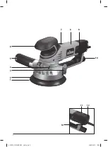
• Push a suitable vacuum hose on to the Dust Extraction Port (10). The Dust
Extraction Port is designed to fit a 32mm diameter hose
Selecting sanding mode
WARNING
: NEVER attempt to operate the Mode Selector Switch (3) whilst the
tool is running. This will cause tool damage.
• This Triton sander features two sanding modes, which can be selected over
the Mode Selector Switch (3) (images B and C):
1. Lift the orange latch and use it to turn the Mode Selector Switch
2. Turn the Mode Selector Switch either clockwise or anticlockwise until it
stops
3. Push the orange latch sideways into the locked position, as shown on the
images below
WARNING
: DO NOT switch on the tool when the Mode Selector Switch is in
between settings, or if the orange latch has not been locked. This will cause
damage to the gears.
Operation
WARNING
: Always use adequate protective equipment, including eye
protection, respiratory and hearing protection, when working with this tool.
WARNING
: DO NOT touch the moving sanding disc.
WARNING
: NEVER allow the sanding disc to completely wear down before
replacing it. Failure to observe these precautionary measures can lead to
damage to the hook and loop surfaces, resulting in sanding discs failing to
attach properly.
Note
: Always use clamps to secure your workpiece to the workbench wherever
possible.
Switching on and off
WARNING
: DO NOT switch the tool on or off whilst under load, as this will
greatly decrease the service life of the On/Off Sliding Switch (7).
1. Connect the plug to the power supply
Note
: The Power Indicator (11) will illuminate when the machine is connected
to mains power.
2. Hold the tool securely with both hands, one on the Main Handle (8), the
other on the Front Grip (3) or Auxiliary Handle (5), and make sure that you
have full control at all times
WARNING
: Despite the electronic soft-start feature, the torque from the motor
can cause the machine to twist when switched on.
3. Ensure the tool is not in contact with the workpiece before commencing
with switching on
4. Push the On/Off Sliding Switch (7) forward until it engages, to start the
machine
532839_Z1MANPRO1_AUS.indd 7
24/02/2015 16:04


