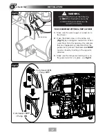
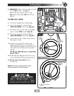
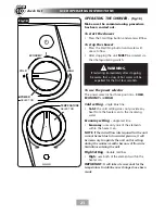
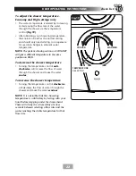
background image

10

ELECTRICAL REQUIREMENTS

3

check list

SECTION

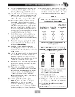
Table B

Note: 

Cable selection is dependent on 

derating factors

Twin and earth PVC insulated cable

Current carrying capacity

In conduit

trunking

6mm²

38A

10mm²

52A

16mm²

69A

Installed in an 

insulated wall

6mm²

32A

10mm²

43A

16mm²

57A

Clipped direct

or buried in a 

non-insulated 

wall

6mm²

46A

10mm²

63A

16mm²

85A

6mm2

10mm2

16mm2

*The method below may be used by

installers to determine the approximate 

size of the incoming cable.

1.

Measure the width of an individual strand,
and half that measurment to find 

(r)

,

e.g: 

1.34mm ÷ 2 = (r) 0.67mm

2.

Multiply 

(r) x (r)

 x 

3.14,

e.g: 

(r)


0.67 x (r)


0.67 

3.14 = 1.41mm2

3.

Multiply this by the number of wire strands
(usually 7), e.g: 

1.41mm2 x 7 = 9.87mm2.

4.

The number obtained would suggest

10mm2

 wiring.

*PLEASE NOTE:

 If unsure, consult a qualified Electrician.

6


A 45 amp double pole isolating switch with 
a minimum contact gap of 3 mm in both 
poles must be incorporated in the circuit.

6.1

  It must have a mechanical indicator showing 

when the switch is in the OFF position, and 
the wiring must be connected to the switch 
without the use of a plug or socket outlet.

6.2

 The switch must be accessible and clearly 

able, but out of reach of a person 

u

xed bath or shower, except for the 

cord of a cord operated switch, and should 
be placed so that it is not possible to touch 
the switch body while standing in a bath or 
shower cubicle. It should be readily accessible 
to switch off after using the shower.

7


Where shower cubicles are located in any 
rooms other than bathrooms, all socket 
outlets in those rooms must be protected by 
a 30mA RCD.

8


The current carrying capacity of the cable 
must be at least that of the shower circuit 
protection 

(see Table B)

.

8.1

  To obtain full advantage of the power 

provided by the shower, use the shortest 
cable route possible from the consumer unit 
to the shower.

8.2

  It is also necessary to satisfy the disconnection 

time and thermal constraints which means 
that for any given combination of current 
demand, voltage drop and cable size, there is 
a maximum permissible circuit length.

9


The shower circuit should be separated from 
other circuits by at least twice the diameter 
of the cable or conduit.

9.1

  The current rating will be reduced if the 

cabling is bunched with others, surrounded 
by thermal loft or wall insulation or placed 
in areas where the ambient temperature 
is above 30°C. Under these conditions, 
derating factors apply and it is necessary to 
select a larger cable size.

9.2

  In the majority of installations 

(see 

Table B)

, the cable will unavoidably be 

placed in one or more of the above 
conditions. This being so, it is strongly 
recommended to use a minimum of 10mm 
cabling throughout the shower installation.

9.3

  In any event, it is essential that individual 

site conditions are assessed by a competent 
electrician in order to determine the correct 
cable size and permissible circuit length.

Summary of Contents for T90SR

Page 1: ... this shower be connected directly to a mains water supply It is designed for GRAVITY FED COLD WATER systems ONLY Failure to comply WILL invalidate product warranty European Union Registered Design No 003154467 0003 0004 The showerhead and hose supplied with this product are a safety critical part of your shower Failure to use genuine Triton parts may cause injury and invalidate your guarantee ...

Page 2: ...he outlet must not be connected to any tap or fitting other than those specified This appliance is intended to be permanently connected to the water mains and not connected by a hose set A suitable double pole isolation switch for supply disconnections must be incorporated in the fixed wiring circuit in accordance with current wiring rules See Electrical Installation section for further details Su...

Page 3: ...ith Water Regulations Building Regulations or any particular regulations as specified by Local Water Company or Water Undertakers and should be in accordance with BS EN 806 2 2 The supply pipe must be flushed to clear debris before connecting to the shower unit 2 3 DO NOT solder pipes or fittings within 300mm of the shower unit as heat can transfer along the pipework and damage components 2 4 DO N...

Page 4: ... not become blocked DO NOT place items such as soap or shampoo bottles on top of the unit Liquid could seep through the joint between the cover and backplate ADVISORY CLEANING It is recommended that all products are cleaned using warm soapy water DO NOT use abrasive or aggressive chemical cleaning products as this may affect the product surface finish and invalidate your guarantee IMPORTANT ADVICE...

Page 5: ...user operating instructions 10 1 2 3 4 5 6 7 8 9 10 Tick off as you complete PLEASE USE THE FOLLOWING CHECK LIST TO AID YOUR INSTALLATION Triton recommend watching the short online videos that cover electric shower basics before your installation videos may not show the exact model purchased What is an electric shower Electrical requirements for electric showers Plumbing requirements for electric ...

Page 6: ...ECK LIST PLEASE FOLLOW COMPLETE SPECIFICATIONS 7 DIMENSIONS CABLE WATER ENTRY POINTS 8 ELECTRICAL REQUIREMENTS 9 10 INSTALLING THE SHOWER 11 20 Siting of the shower 11 12 Plumbing installation 13 Electrical installation 14 Fit to the wall connect the shower supplies 14 16 Installation 17 18 COMMISSIONING PROCEDURE 19 20 USER OPERATING INSTRUCTIONS FUNCTIONS 21 23 Cleaning the filter installers ser...

Page 7: ...nimum inlet temperature 2 C Inlet connection 15mm diameter Outlet connection BSP male thread MATERIALS ABS Backplate cover controls showerhead Acetal Sprayplate Minerally insulated corrosion resistant metal sheathing Elements STANDARDS and APPROVALS Splashproof rating IP25 Safety Complies with the requirements of current British and European safety standards for household and similar electrical ap...

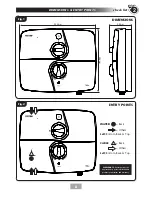
Page 8: ...ECTION Fig 2 Fig 1 ENTRY POINTS DIMENSIONS CABLE Left Bottom Back Top Back Others 322mm 95mm 266mm WATER Left Bottom Back Top Back Others PLEASE NOTE Deviation from the approved entry points will invalidate product specifications and warranty ...

Page 9: ...f in any doubt switch off the whole installation at the mains supply and remove the correct fuse 3 The shower must be connected to its own independent electrical circuit IT MUST NOT be connected to a ring main spur socket outlet lighting circuit or cooker circuit 3 1 The electrical supply must be adequate for the loading of the unit and existing circuits 4 Check your consumer unit main fuse box ha...

Page 10: ... while standing in a bath or shower cubicle It should be readily accessible to switch off after using the shower 7 Where shower cubicles are located in any rooms other than bathrooms all socket outlets in those rooms must be protected by a 30mA RCD 8 The current carrying capacity of the cable must be at least that of the shower circuit protection see Table B 8 1 To obtain full advantage of the pow...

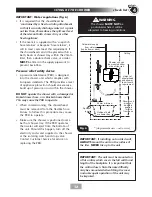
Page 11: ...mance from the unit throughout the year During periods of high ambient temperatures it may be necessary to select the economy power setting to achieve your preferred shower temperature Fig 5 shows a typical system layout Refer to fig 6 for the correct siting of the shower Position the unit where it will NOT be in direct contact with water from the showerhead Position the shower unit vertically All...

Page 12: ...ay cause the PRD to operate When commissioning the showerhead must be removed from the flexible hose Failure to follow this procedure may cause the PRD to operate Make sure the shower is positioned over a bath or shower tray If the PRD operates then water will eject from the bottom of the unit Should this happen turn off the electricity and water supplies to the shower at the isolating switch and ...

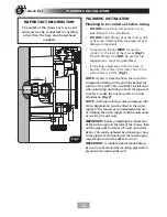
Page 13: ...ng and tiling around the pipework in order to make the nut accessible for future adjustments fig 7 NOTE A fullway isolating valve complying with Water Regulations must be fitted in the water supply to the shower as an independent means of isolating the water supply should maintenance or servicing be necessary IMPORTANT Before completing the connection of the water supply to the inlet of the shower...

Page 14: ...t trim that may be cut as shown in fig 8 to accommodate either pipe or electric cable entry The bottom trimplate has a cut out access point for pipe electric Decide on the pipe and electric entry required Once chosen remove either the top trim or appropriate cut out section using a junior hacksaw and file or suitable knife 6 check list 7 check list SECTION SECTION PLEASE NOTE The cut out is NOT de...

Page 15: ...ing holes are elongated to allow for out of square adjustment after the plumbing connection has been completed Connect the water supply to the inlet DO NOT use excessive force when making the connection Make sure the backplate is square on the wall and tighten the retaining screws which hold it in place Turn on the water supply and check for leaks in the pipework connection to the shower IMPORTANT...

Page 16: ... screws Loose connections can result in cable overheating NOTE The supply cable earth conductor must be sleeved The outer sheath of the supply cable must be stripped back to the minimum The use of connections within the unit or other points in the shower circuit to supply power to other equipment i e extractor fans pumps etc will invalidate the guarantee DO NOT switch on the electricity supply unt...

Page 17: ...he opening this indicates that any trapped air is vented and that the pump unit is primed The bleed valve MUST now be closed by rotating in the opposite direction 3 Make sure the temporary locking screw on the power selector is in place see fig 10 Fig 13 Fig 14 Commission ON Pump OFF Bleed screw Open Commission OFF Pump ON WARNING Before fitting the cover the following list MUST be checked to ensu...

Page 18: ...r on lens 10 Check to ensure that the wiring is not trapped and replace the cover squarely to the backplate and guide into position so that the knobs locate correctly into the splined spindles Should any difficulty arise recheck the points above 11 While applying slight pressure to the cover secure in position with the retaining screws 12 Fit the riser rail and kit see kit instructions NOTE The kn...

Page 19: ... to fully anti clockwise to MAXIMUM flow fig 17 2 Turn on the electric supply to the shower at the isolating switch 3 Press the Start Stop button and wait until water starts to flow from the flexible hose At least 30 seconds 4 Once flushing out has been completed stop the water flow by pressing the Start Stop button WARNING Before normal operation of the shower it is essential the following commis...

Page 20: ...e for future use Make sure the selector spindle is left at the same position 8 Check to ensure that the wiring is not trapped and replace the cover squarely to the backplate and guide into position so that the knobs locate correctly into the splined spindles Should any difficulty arise recheck the points above 9 While applying slight pressure to the cover secure in position with the retaining scre...

Page 21: ...ctor has three positions COLD ECONOMY and HIGH Cold setting single blue line Cold the cold setting does not provide any heat from the heater can to the incoming water Economy setting single red line Economy uses only one of the elements within the heater can NOTE If the stated flow rate required for the unit cannot be met due to low water pressure it will be necessary to operate the unit on this s...

Page 22: ...give a different temperature to the same position on HIGH To decrease the shower temperature Turning the temperature control anti clockwise will increase the flow of water through the shower and make the water cooler To increase the shower temperature Turning the temperature control clockwise will decrease the flow of water through the shower and make the water warmer NOTE It is advisable that the...

Page 23: ...erature Protection During normal operation if the temperature exceeds the showering safety limit the power to the elements will be removed completely although water will continue to flow When the temperature has cooled sufficiently power to the elements will be automatically restored to the settings at the time of interruption Abnormal Safety cut out The unit is fitted with a non resettable therma...

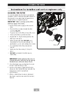
Page 24: ...ew the filter cap from the inlet Inspect the O ring for damage when the filter cap is removed When cleaning the filter DO NOT use a sharp object as it will cause damage It is preferable to use an old toothbrush or similar To reassemble follow the procedure in reverse Make sure that the sealing O ring is in place DO NOT over tighten the filter cap on reassembly IMPORTANT Before replacing the cover ...

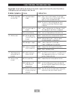
Page 25: ...f a blockage in the inlet filter 2 3 Increase in ambient water temperature 2 3 1 Readjust flow rate to give increased flow 2 3 2 Select economy power 3 Water temperature cycling hot cool at intervals 3 1 Heater cycling on thermal cut out 3 1 1 See Water too hot causes 2 1 2 2 and 2 3 and their appropriate action cures If it continues contact Customer Service 4 Water too cool or cold 4 1 Too much f...

Page 26: ... from the cistern during showering 6 1 5 Reprime the unit without electricity switched on to the unit see commissioning 7 Pressure relief device has operated water ejected from the PRD 7 1 Blocked showerhead 7 1 1 Clean or replace blocked showerhead and then fit a new PRD 7 2 Twisted blocked flexible shower hose 7 2 1 Check for free passage through the hose Replace the hose if necessary then fit a...

Page 27: ...27 SPARE PARTS 10 7 6 5 4 1 3 8 2 13 11 9 16 1 9 12 6 8 2 4 7 13 3 10 5 14 14 15 17 11 12 ...

Page 28: ...utlet Pipe Assembly S85000251 8 Switch Carriage Top P82500281 Ref Description Part No 9 Start Stop Switch Assembly P81901350 10 Trimplate White 7054251 Trimplate Satin 7054287 11 Microswitch Wire Assembly P07810903 12 Microswitch Wire Assembly P82301740 13 Power LED P81901334 14 Motor Power Supply 7073750 15 PRD 82800450 16 Pipe Trim White 7054250 Pipe Trim Satin 7054288 17 Cover Assembly White P8...

Page 29: ...2 HEATER ELEMENTS USED HEATER ELEMENTS USED NONE OF THE ELEMENTS USED 0 1 2 1 OF THE ELEMENTS USED HEATER ELEMENTS USED 2 OF THE ELEMENTS USED 0 1 2 H O T HOT COLD The power light will illuminate 3 4 To STOP the shower press the Start Stop button then turn the isolator switch OFF 2 To start the shower press the Start Stop button To START or STOP your shower To alter the FLOW and TEMPERATURE of you...

Page 30: ...30 ...

Page 31: ...31 ...

Page 32: ...yment should be made by credit debit card excluding American Express or Diners Card Payment can also be made by pre payment of a pro forma invoice by cheque or postal order Telephone orders are based on information given during the call Before contacting Triton please verify your requirements using the Information contained in the user guide Triton cannot accept liability for incorrect part identi...

Reviews: