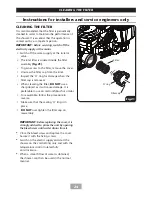
11
SITING OF THE SHOWER
SITING OF THE SHOWER
The installation must be in accordance with
Water Regulations/Bylaws -
see page 7 and
below for water specifications.
• To ensure activation of the heating elements,
the shower must be connected to a cold
water supply which is gravity fed from a
static cold water storage cistern with a
minimum capacity of 114 litres (25 gallons)
that will deliver a
MINIMUM
of 8 litres per
minute to the shower water inlet.
• There must be a maximum head of water of
10 metres and a minimum head of 8 cm as
measured between the bottom of the cistern
and the top of the shower unit. There must
be no other cold water draw-offs between
the cistern and the unit and the pipe must
not supply water to any other tap or fitting
at a lower level.
• Pipework to the shower unit
MUST
be
routed where it remains below the level of
the water cistern.
• If it is intended to operate the shower at
pressures above the maximum or below the
minimum stated, contact Customer Service
for advice.
• If the stated flow rates are not available,
it may not be possible to achieve optimum
performance from the unit throughout
the year.
• During periods of high ambient temperatures
it may be necessary to select the economy
power setting to achieve your preferred
shower temperature.
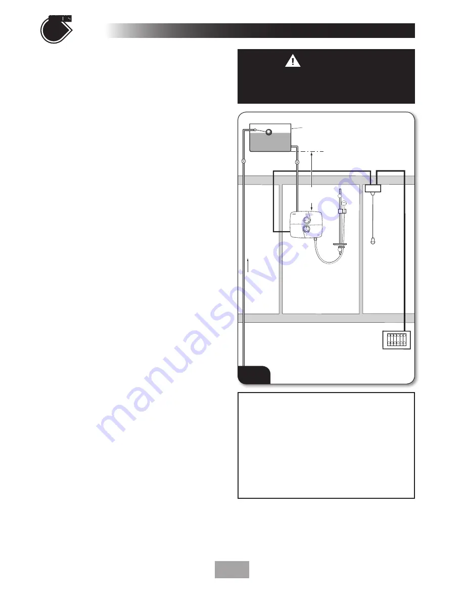
Fig.5
shows a typical system layout.
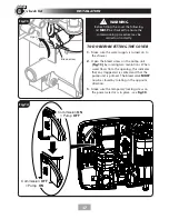
• Refer to
fig.6
for the correct siting of the
shower. Position the unit where it will
NOT
be in direct contact with water from
the showerhead. Position the shower unit
vertically.
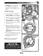
• Allow enough room between the ceiling and
the shower to access the cover top screws.
• Mark out entry points and routing of the
water and electric supplies into the shower.
4
check list
SECTION
Mains
water
supply
Gate
valve
Stop
valve
Cold water
cistern
Mains electric supply
(via double pole switch)
Double
pole
isolating
switch
Separate permanently
connected supply
from consumer unit
Shower
unit
Minimum capacity
114 litres (25 gallons)
8 cm (3")
minimum
WARNING
UNDER NO CIRCUMSTANCES
should
this shower be connected directly to
the mains water supply.
Diagrammatic view (not to scale)
Fig.5
ADVISORY NOTE
The supply pipe from the cistern should be
on the opposite side to the float operated
valve to prevent air being drawn into the
pipe when the cistern is filling.
If it is intended to operate the shower in
hard water areas (above 200 ppm temporary
hardness) a scale inhibitor should be fitted.
Summary of Contents for T90SR
Page 27: ...27 SPARE PARTS 10 7 6 5 4 1 3 8 2 13 11 9 16 1 9 12 6 8 2 4 7 13 3 10 5 14 14 15 17 11 12 ...
Page 30: ...30 ...
Page 31: ...31 ...


