18
INSTALLATION
8
check list
SECTION
4. IMPORTANT:
Make sure the commission link
is in the
ON
position - see
fig.14
.
NOTE: With the commission link in the
ON
position the pump is
OFF
and will not
operate.
FITTING THE COVER
5.
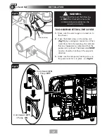
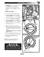
Locate the trimplate into the backplate.
6.
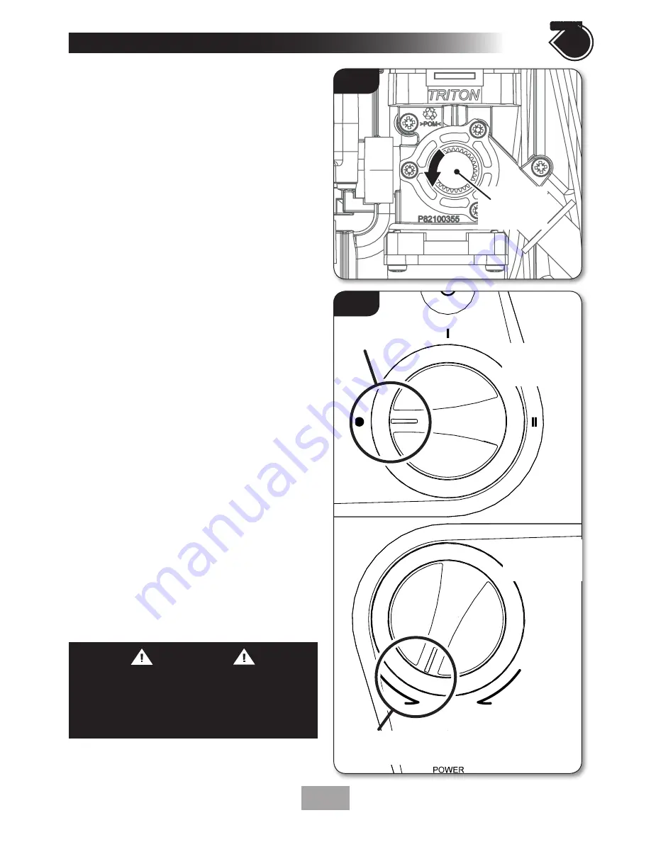
Turn the temperature control spindle
ANTI-CLOCKWISE
until it stops
(fig.15)
.
7.
The power selector knob must be aligned as
shown, to the
COLD
position
(fig.16)
.
8.
Turn the temperature control knob fully
ANTI-CLOCKWISE
until it stops
(fig.16)
.
9.
Clip the LED into the holder on the back of
the ‘power on’ lens.
10.
Check to ensure that the wiring is not
trapped and replace the cover squarely to
the backplate and guide into position so that
the knobs locate correctly into the splined
spindles.
Should any difficulty arise, recheck the
points above.
11.
While applying slight pressure to the cover,
secure in position with the retaining screws.
12. Fit the riser rail and kit
(see kit
instructions).
NOTE:
The knobs should be left in these
positions ready for commissioning.
Fig.16
COLD
position
Fully anti-clockwise
position
POWER
SELECTOR
KNOB
TEMPERATURE
CONTROL
KNOB
Fig.15
Turn the
spindle until
it stops
WARNING
COVER RETAINING SCREWS
ONLY
the
SUPPLIED SCREWS
should be
used. The use of none supplied screws
WILL
invalidate product specifications & warranty.
Summary of Contents for T90SR
Page 27: ...27 SPARE PARTS 10 7 6 5 4 1 3 8 2 13 11 9 16 1 9 12 6 8 2 4 7 13 3 10 5 14 14 15 17 11 12 ...
Page 30: ...30 ...
Page 31: ...31 ...

