8
Unpacking Your Tool
• Carefully unpack and inspect your tool. Familiarise yourself with all its features and functions.
• Ensure that all parts of the tool are present and in good condition. If any parts are missing or
damaged, have such parts replaced before attempting to use this tool.
Before Use
Removing a battery
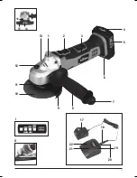
• To remove the Battery (5) from the angle grinder, press the Battery Release (6), then slide
the Battery off the base of the tool
WARNING:
DO NOT try to remove the Battery without pressing the Battery Release button. The
grinder or Battery could be damaged.
Fitting a battery
1. To fit a charged battery, slide it on to the base of the tool until it clicks and locks into position
Note:
Make sure the Battery and base are lined up correctly. If the Battery does not slide into the
base easily, do not force it. Instead, slide the Battery out of the base, check the top of Battery and
the tool battery slot are clean and undamaged and that the contacts are not bent.
Setting up the battery charger
1. Insert the PSU DC Plug (18) into the Charger DC Socket (20)
2. If fitted, remove any existing battery from the Battery Charger (19)
3. Insert the Charger PSU (17)into a suitable mains socket
Note:
The Green LED (21) on the Battery Charger will flash to indicate that the charger is ready
to charge the battery.
WARNING:
Use this charger ONLY to charge the supplied battery or additional purchased
batteries that are specifically designed for this tool.
WARNING:
The charger is designed for indoor use only, and MUST NOT be used in damp or wet
conditions.
Charging the battery
WARNING:
Failure to follow the correct procedure when charging batteries will result in
permanent damage.
1. Slide the Battery Charger (19) onto a fully or partially discharged Battery
Note:
Make sure the Battery and Battery Charger are lined up correctly. If the Battery does not
slide on to the Battery Charger easily, don’t force it. Instead, remove the Battery, check the top of
Battery and the Battery Charger slot are clean and undamaged and that the contacts are not bent.
2. Once charging commences, the Red LED (22) will illuminate
3. When the Battery is fully charged, the Green LED (21) will be illuminated
Battery Charge Level:
The battery has a built-in Charge Indicator (4) (Fig. I). Pressing on the
button to the right will indicate the charge level. The right LED indicates a high charge level and
the left a low charge level that will mean the battery pack will require charging soon.
IMPORTANT:
When a low charge level is indicated, the tool may stop operating while in use. In
some instances this may be dangerous. Always ensure the battery pack has a good charge level.
Note
: Due to the high current motor of this tool and safety issues with the battery fully discharging
in use stopping the tool operating, it is recommended to use a minimum of 2.0Ah capacity
batteries (XT2AHB).
Notes about battery charging:
• The battery should be charged at ambient temperatures between 10 and 40°C
(ideally around 20°C)
• After charging, allow 15 minutes for the battery to cool before use
• Ensure that the charger is disconnected from the mains supply after use, and is stored
correctly
• DO NOT leave batteries on charge for extended periods and NEVER store batteries on charge
• The Battery Charger monitors battery temperature and voltage while charging. Remove the
Battery once charging has been completed to maximise charge cycles of the battery and not
waste power
• Batteries can become faulty over time, individual cells in the battery can fail and the battery
could short. The charger will not charge faulty batteries. Use another battery, if possible, to
check correct functionality of the charger and purchase a replacement battery if a faulty
battery is indicated
• DO NOT store lithium-ion battery packs in a discharged state long term. This can damage the
lithium-ion cells. For long-term storage, store batteries in a high charge state disconnected
from the power tool
• The capacity of batteries will reduce over time. After 100 charge cycles, the battery’s
operation time and the maximum torque performance of the angle grinder will slightly
reduce. This decline will continue until the battery has minimal capacity after 500 charge
cycles. This is normal and not a fault with the battery pack
Angle grinder set-up
WARNING:
Always disconnect the battery pack from the angle grinder before attempting to fit or
replace any attachment. Never fit any attachment with a maximum speed lower than the no load
speed of the machine.
• All discs and accessories must be subjected to a visual inspection prior to installation, to
ensure they are in good condition and within their expiry date. If in doubt, DO NOT USE AND
DISCARD
• Always check all parts and attachments are secure, and that rotating parts will not foul on
guards or machine case
• Always hold the machine, using both hands, by the handles provided
• Be aware that the cast metal gear housing may get hot during use
• Hot air will be emitted from the ventilation holes
• Ensure that the ventilation holes are not obscured in any way
• Always wear appropriate personal protective equipment for the task. Use of this machine
requires ear defenders, eye protection, gloves, breathing protection, and if appropriate
a hard hat
Fitting the auxiliary handle
WARNING:
To ensure operator safety, ALWAYS use the Auxiliary Handle (8). Install it at the most
appropriate position for the individual task.
1. Screw the Auxiliary Handle clockwise into one of the three Handle Mounting Points (1 & 13)
of the gear housing. Tighten by hand
Note:
The auxiliary handle can be mounted to the left or right hand side of the Gear Housing.
2. To remove the handle, unscrew anti-clockwise
Adjusting, removing and installing the wheel guards
WARNING:
The correct guard MUST be installed for each application before operation
commences. This is an essential safety requirement.
WARNING:
NEVER install a cutting disc or superabrasive cutting wheel without the correct cutting
wheel guard (optional accessory) in place.
Note:
The guard must be adjusted so that it is situated between the disc and the operator. Reset
the guard if the work angle or the position of the operator changes. Seek professional guidance if
you are unsure how to operate the guards or any other safety features of the machine correctly.
Note:
The grinder is supplied with the Grinding Guard (9) pre-installed.
Adjusting the guard
1. Release the Guard Quick-Release (11)
2. The Grinding Guard can be moved through a range of approximately 90°, so that it can be
placed between the disc and the operator at any required work angle
3. Tighten the hex screw on the Grinding Guard securely
Note:
If the clamp is too loose or too tight, open completely and adjust the lever tightening screw.
Removing Guard
Note
: Skip Step 1 if no disc is installed.
1. Depress the Spindle Lock Button (12), rotate the Spindle (14) until you feel the lock engage.
Use the Pin Spanner (7) to remove the Outer Flange (15) and remove the disc
2. Use the Guard Quick Release (11) on the Grinding Guard (9). Pull the Grinding Guard over
both of the flanges, and remove from the tool
Installing Guard
1. Release the Quick Release located on the Grinding Guard (9)
2. Fit the clamp of the Grinding Guard over the neck of the grinder
3. Tighten the Quick Release on the Grinding Guard securely
• An optional cutting guard may have a different securing mechanism. Follow the instructions
provided with the accessory.
Fitting a grinding or cutting disc
Note:
Ensure you have the correct guard installed for the disc you plan to install.
1. Ensure that the Inner Flange (16) is in place on the Spindle (14) and positively engaged
with the spindle flats
2. Place the cutting or grinding disc onto the inner flange
Note:
If using depressed centre discs, ensure that the depression is positioned towards the
inner flange.
3. Screw the Threaded Outer Flange (15) onto the Spindle (14). The raised centre of the
Threaded Outer Flange should face towards the disc when installing a grinding disc, and
away when installing a cutting disc
4. Depress the Spindle Lock Button (12) and rotate the Spindle until the lock engages
5. Use the supplied Pin Spanner (7) to fully tighten the threaded Outer Flange. When tight,
release the Spindle Lock Button. The grinder is now ready for use
6. To remove a disc, depress the Spindle Lock Button, rotate the spindle until you feel the lock
engage, and use the Pin Spanner to remove the Outer Flange
Fitting a wire cup brush
Note: When using the angle grinder with wire cup brushes, the guards become ineffective and
should be removed.
1. Remove Threaded Outer Flange (15), Grinding Disc (10) (if installed) and Inner Flange (16)
from the Spindle (14)
2. Screw cup brush directly onto spindle
3. Depress the Spindle Lock Button (12) and rotate the Spindle until you feel the lock engage
4. Tighten the cup brush with a suitable spanner. Release the Spindle Lock Button.
The machine is now ready for use
5. To remove a cup brush, depress the spindle lock button, rotate the spindle until you feel the
lock engage, then use a suitable spanner to remove the cup brush
814386_Z1MANPRO1.indd 8
06/08/2015 09:59
Summary of Contents for XT18
Page 1: ...tritontools com XT CAG115B Angle Grinder 115mm ...
Page 2: ...2 ...
Page 3: ...3 10 11 12 13 1 2 3 4 5 6 7 8 9 I POWER LEVEL PRESS II 15 16 15 14 22 21 19 20 17 18 ...
Page 11: ...11 Notes ...
Page 12: ......

