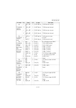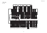
3NB/3ND/3N0/3NK-2
2-3-18
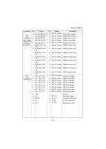
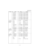
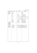
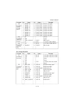
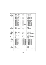
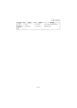
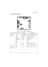
YC2
1
DECAL_DIR
O
0/3.3V DC
BRDM drive change signal
Connected to
the engine
PWB
2
DECAL_PD
O
0/3.3V DC
BRDM control signal
3
DECAL_CLK
O
0/3.3V DC(pulse)
BRDM clock signal
4
DECAL_MODE
O
0/3.3V DC
BRDM control signal
5
DECAL_REM
O
0/3.3V DC
BRDM: On/Off
6
GUIDE_DIR
O
0/3.3V DC
BRGM drive change signal
7
GUIDE_PD
O
0/3.3V DC
BRGM control signal
8
GUIDE_CLK
O
0/3.3V DC(pulse)
BRGM clock signal
9
GUIDE_REM
O
0/3.3V DC
BRGM: On/Off
10
DECAL_HP_SENS
I
0/3.3V DC
BRDS: On/Off
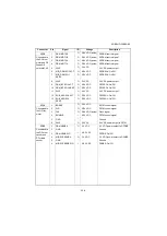
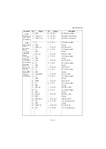
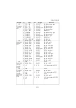
YC3
1
BRIDGE_SENS 1
O
0/5V DC
BRCS1: On/Off
Connected to
the engine
PWB
2
BRIDGE OPEN
O
0/5V DC
BRCUSW: On/Off
3
BRIDGE_SENS 2
O
0/5V DC
BRCS2: On/Off
4
BRIDGE1 DIR
I
0/5V DC
BRCM1 control signal
5
BRIDGE1 PD
I
0/5V DC
BRCM1 control signal
6
BRIDGE1 CLK
I
0/5V DC(pulse)
BRCM1 clock signal
7
BRIDGE1 MODE
I
0/5V DC
BRCM1 mode signal
8
BRIDGE1 REM
I
0/5V DC
BRCM1: On/Off
9
BRIDGE2 DIR
I
0/5V DC
BRCM2 control signal
10
BRIDGE2 PD
I
0/5V DC
BRCM2 control signal
11
BRIDGE2 CLK
I
0/5V DC(pulse)
BRCM2 clock signal
12
BRIDGE2 MODE
I
0/5V DC
BRCM2 mode signal
13
BRIDGE2 REM
I
0/5V DC
BRCM2: On/Off
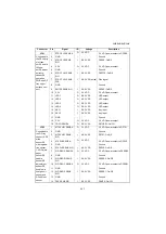
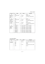
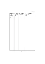
YC4
1
GND
-
-
Ground
Connected to
the bridge
conveying
sensor 2
2
BRIDGE_SENS 2
I
0/5V DC
BRCM2: On/Off
3
+5V
O
5V DC
5 V DC power output to BRCS2
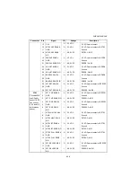
YC6
1
GND
-
-
Ground
Connected to
the bridge
conveying
sensor 2 and
bridge cover
switch
2
BRIDGE_SENS 1
I
0/5V DC
BRCS1: On/Off
3
+5V
O
5V DC
5 V DC power output to BRCS1
4
GND
-
-
Ground
5
BRIDGE_OPEN
I
0/5V DC
BRCUSW: On/Off
6
+5V
O
5V DC
5 V DC power output to BRCUSW
7
NC
-
-
Not used
Connector
Pin
Signal
I/O
Voltage
Description
Summary of Contents for UTAX AK 730
Page 5: ...This page is intentionally left blank ...
Page 11: ...This page is intentionally left blank ...
Page 15: ...3NB 3ND 3N0 3NK This page is intentionally left blank ...
Page 25: ...3NB 3ND 3N0 3NK 1 1 10 This page is intentionally left blank ...
Page 43: ...3NB 3ND 3N0 3NK 1 2 18 3 Remove tape and pad Figure 1 2 23 Tape Pad ...
Page 45: ...3NB 3ND 3N0 3NK 1 2 20 This page is intentionally left blank ...
Page 81: ...3NB 3ND 3N0 3NK 1 3 36 This page is intentionally left blank ...
Page 157: ...3NB 3ND 3N0 3NK 1 4 76 This page is intentionally left blank ...
Page 169: ...3NB 3ND 3N0 3NK 1 5 12 This page is intentionally left blank ...
Page 206: ...3NB 3ND 3N0 3NK 2 2 11 This page is intentionally left blank ...
Page 246: ...1 1 INSTALLATION GUIDE INSTALLATION GUIDE FOR 4000 SHEETS FINISHER ...
Page 269: ...INSTALLATION GUIDE FOR FINISHER ATTACHMENT KIT MFP A ...
Page 283: ...INSTALLATION GUIDE FOR FINISHER ATTACHMENT KIT MFP B ...
Page 284: ...E F A H G I J B D C ...
Page 291: ...INSTALLATION GUIDE FOR FINISHER ATTACHMENT KIT PRINTER ...
Page 295: ...INSTALLATION GUIDE FOR CENTER FOLDING UNIT ...
Page 312: ...INSTALLATION GUIDE FOR MULTI TRAY ...
Page 326: ...INSTALLATION GUIDE FOR MULTI TRAY ATTACHMENT KIT PRINTER ...
Page 330: ...INSTALLATION GUIDE FOR PUNCH UNIT ...


