8
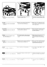
F
32
O
2
2
1
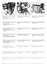
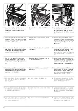
17.
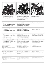
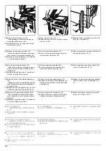
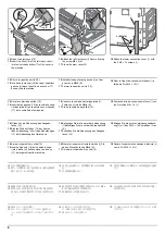
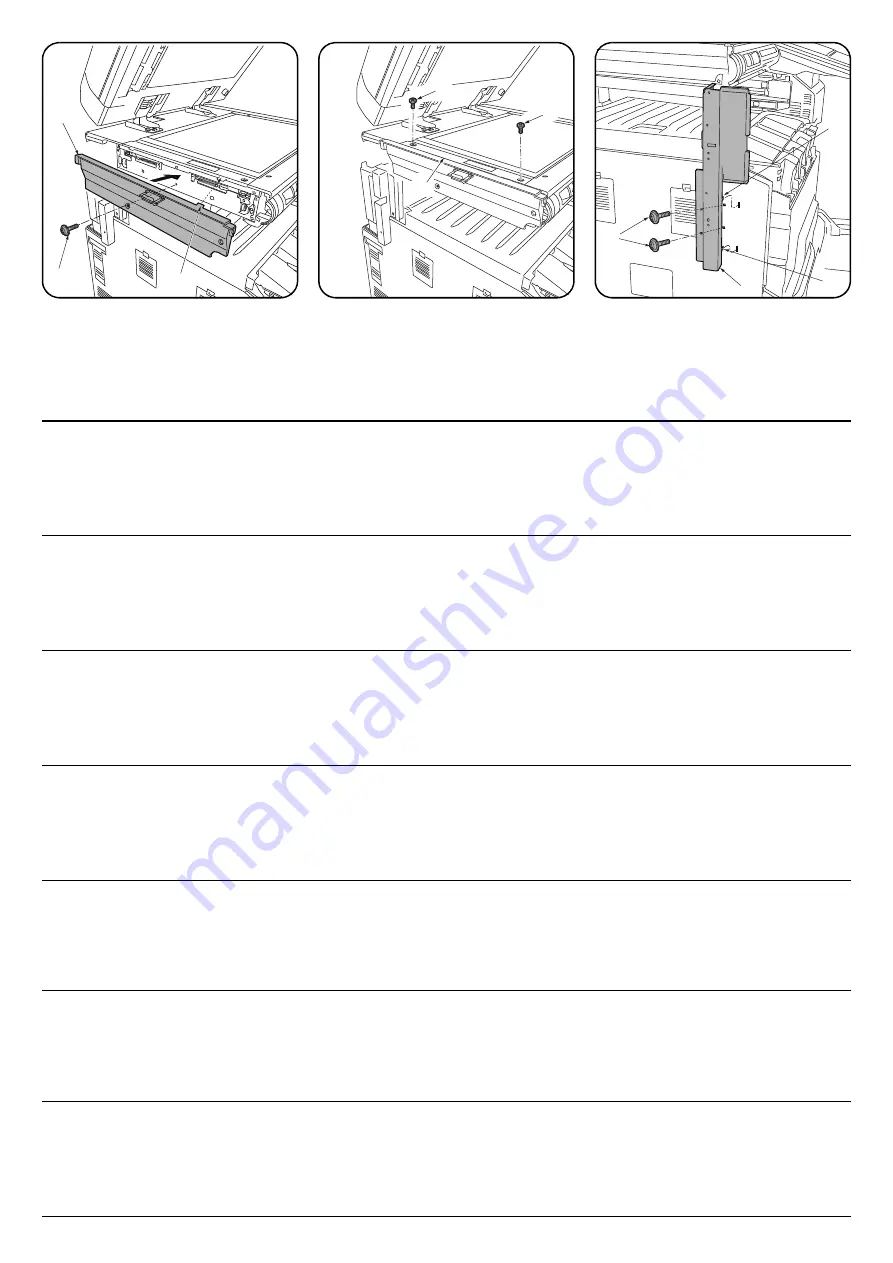
Insert the hook (32) on the left scanner cover
(F) into the hole in the side plate and secure
the left scanner cover (F) with the M4 × 8
screw (O).
18.
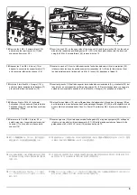
Mount the 2 screws (2) in the left ISU cover
(1).
19.
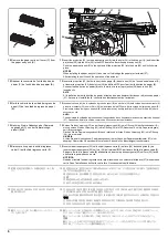
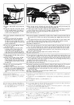
Insert the 2 projections (33) on the front left
stay (G) into the holes in the left cover on the
MFP and temporarily fasten the front left
stay (G) in place with the 2 M4 × 20 screws
(P).
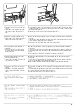
17.
Insérer le crochet (32) du couvercle de scan-
ner gauche (F) dans le trou de la tôle latérale
et fixer le couvercle de scanner gauche (F) à
l'aide d'une vis M4 × 8 (O).
18.
Déposer les 2 vis (2) du couvercle gauche
de l'ISU (1).
19.
Insérer les 2 projections (33) du support
avant gauche (G) dans les trous du couver-
cle gauche du MFP et fixer provisoirement le
support avant gauche (G) à l'aide de 2 vis
M4 × 20 (P).
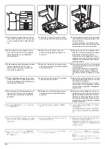
17.
Inserte el gancho (32) de la cubierta izqui-
erda del escáner (F) en el orificio de la placa
lateral y asegure la cubierta izquierda del
escáner (F) con el tornillo M4 × 8 (O).
18.
Instale los 2 tornillos (2) en la cubierta ISU
izquierda (1).
19.
Inserte los 2 salientes (33) del soporte fron-
tal izquierdo (G) en los orificios de la cubi-
erta izquierda de la MFP y ajuste
temporariamente el soporte frontal izquierdo
(G) en posición con los 2 tornillos M4 × 20
(P).
17.
Setzen Sie den Haken (32) an der linken
Scanner-Abdeckung (F) in die Öffnung der
Seitenplatte und sichern Sie die linke Scan-
ner-Abdeckung (F) mit der M4 × 8 Schraube
(O).
18.
Befestigen Sie die 2 Schrauben (2) an der
linken ISU-Abdeckung (1).
19.
Setzen Sie die 2 Vorsprünge (33) der vor-
deren linken Stütze (G) in die Öffnungen der
linken Abdeckung am MFP ein und befesti-
gen Sie die vordere linke Stütze (G) provi-
sorisch mit den 2 M4 × 20 Schrauben (P).
17.
Inserire il gancio (32) sul coperchio sinistro
dello scanner (F) nel foro della piastra later-
ale e fissare il coperchio sinistro dello scan-
ner (F) con la vite M4 × 8 (O).
18.
Montare le 2 viti (2) sul coperchio sinistro
dell'ISU (1).
19.
Inserire le 2 parti sporgenti (33) sul supporto
anteriore sinistro (G) nei fori nel coperchio
sinistro sull'MFP e stringere temporanea-
mente il supporto anteriore sinistro (G) in
posizione con le 2 viti M4 × 20 (P).
17.
スキャナー左カバー(F) のフック (32) を側
板の穴に入れて、ビス M4×8(O)1 本でスキャ
ナー左カバー(F) を固定する。
18.
ISU 左カバー(1) のビス (2)2 本を取り付け
る。
19.
左前ステー(G) の 2 箇所の突起 (33) を MFP
本体の左カバーの穴に入れ、ビス M4×20(P)
2 本で左前ステー(G) を仮締めする。
17.
将扫描仪左盖板 (F) 的卡扣 (32) 插入侧板的
孔中,使用 1 颗 M4×8 螺丝 (O) 螺丝来固定
扫描仪左盖板 (F)。
18.
安装 ISU 左盖板 (1) 的 2 颗螺丝 (2)。
19.
将左前部支架 (G) 的 2 处突出部 (33) 插入
MFP 主机的左盖板的孔中,使用 2 颗 M4×20
螺丝 (P) 临时固定左前部支架 (G)。
17.
스캐너 좌측커버 (F) 의 후크 (32) 를 측면판
의 구멍에 넣고 나사 M4×8(O) 1 개로 스캐
너 좌측커버 (F) 를 고정합니다 .
18.
ISU 좌측 커버 (1) 의 나사 (2) 2 개를 고정합
니다 .
19.
좌측 앞 받침대 (G) 의 돌기 (33) 2 군데를
MFP 본체의 좌측커버의 구멍에 넣고 나사
M4×20(P) 2 개로 좌측앞 받침대 (G) 를 반
정도 조입니다 .
33
33
P
G
Summary of Contents for UTAX AK 730
Page 5: ...This page is intentionally left blank ...
Page 11: ...This page is intentionally left blank ...
Page 15: ...3NB 3ND 3N0 3NK This page is intentionally left blank ...
Page 25: ...3NB 3ND 3N0 3NK 1 1 10 This page is intentionally left blank ...
Page 43: ...3NB 3ND 3N0 3NK 1 2 18 3 Remove tape and pad Figure 1 2 23 Tape Pad ...
Page 45: ...3NB 3ND 3N0 3NK 1 2 20 This page is intentionally left blank ...
Page 81: ...3NB 3ND 3N0 3NK 1 3 36 This page is intentionally left blank ...
Page 157: ...3NB 3ND 3N0 3NK 1 4 76 This page is intentionally left blank ...
Page 169: ...3NB 3ND 3N0 3NK 1 5 12 This page is intentionally left blank ...
Page 206: ...3NB 3ND 3N0 3NK 2 2 11 This page is intentionally left blank ...
Page 246: ...1 1 INSTALLATION GUIDE INSTALLATION GUIDE FOR 4000 SHEETS FINISHER ...
Page 269: ...INSTALLATION GUIDE FOR FINISHER ATTACHMENT KIT MFP A ...
Page 283: ...INSTALLATION GUIDE FOR FINISHER ATTACHMENT KIT MFP B ...
Page 284: ...E F A H G I J B D C ...
Page 291: ...INSTALLATION GUIDE FOR FINISHER ATTACHMENT KIT PRINTER ...
Page 295: ...INSTALLATION GUIDE FOR CENTER FOLDING UNIT ...
Page 312: ...INSTALLATION GUIDE FOR MULTI TRAY ...
Page 326: ...INSTALLATION GUIDE FOR MULTI TRAY ATTACHMENT KIT PRINTER ...
Page 330: ...INSTALLATION GUIDE FOR PUNCH UNIT ...

