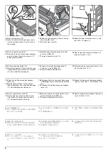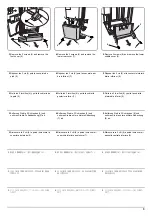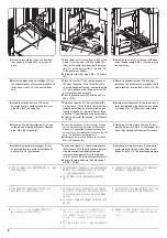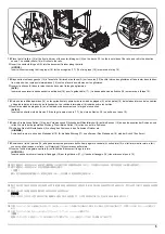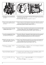
3
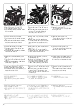
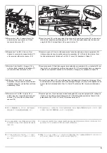
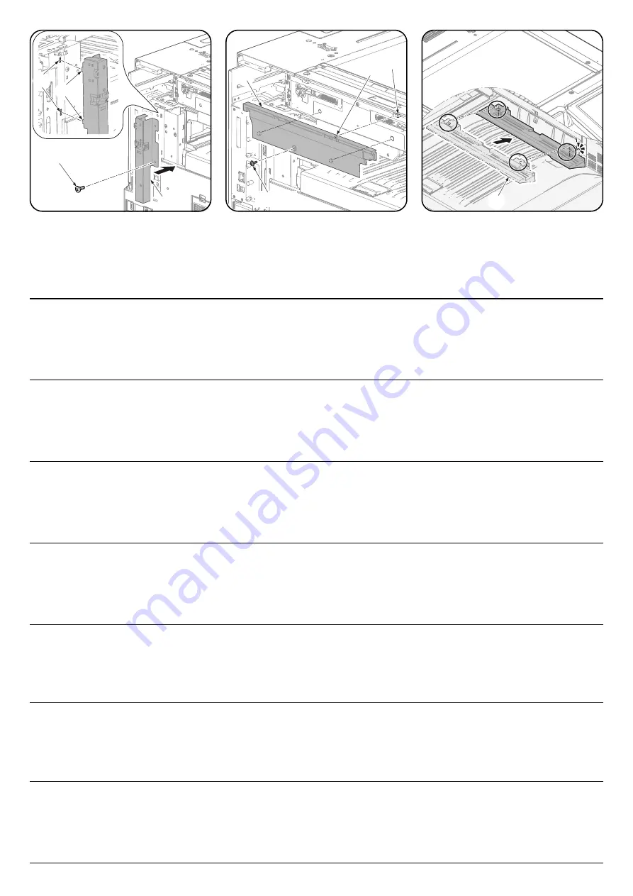
3.
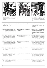
Insert the two projections(4) on the left rear
stay(A) into the holes(5) in the frame.Secure
the left rear stay(A) with the screw(1)
removed in step 1.
4.
Insert the hook(6) on the left cover of the
scanner(B) into the hole(7) in the
frame.Secure the left cover(B) of the scan-
ner with the screw(1) removed in step 1.
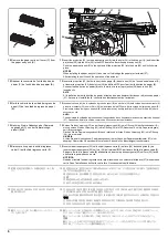
5.
Align the projection of the rail AK(C) with the
hole of the tray cover.
(Fit it until it clicks into place.)
3.
Introduire les deux ergots (4) du support arri-
ère gauche (A) dans les trous (5) du cadre.
Fixer le support arrière gauche (A) avec la
vis (1) retirée à l'étape 1.
4.
Introduire le crochet (6) sur le capot gauche
du scanner (B) dans le trou (7) du cadre.
Fixer le capot gauche (B) du scanner avec la
vis (1) retirée à l'étape 1.
5.
Aligner l'ergot du rail AK (C) avec le trou du
capot de bac.
(Un déclic indique que la pièce est en posi-
tion.)
3.
Inserte las dos proyecciones (4) de la estan-
cia izquierda posterior (A) en los orificios (5)
del marco.Fije la estancia izquierda posterior
(A) con el tornillo (1) que quitó en el paso 1.
4.
Inserte el enganche (6) de la cubierta izqui-
erda del escáner (B) en el orificio (7) del
marco.Fije la cubierta izquierda (B) del
escáner con el tornillo (1) que quitó en el
paso 1.
5.
Alinee la proyección del AK del raíl (C) con
el orificio de la cubierta de la bandeja.
(Ajústela hasta que escuche un clic de posi-
cionamiento.)
3.
Setzen Sie die beiden Nasen (4) des linken
hinteren Anschlags (A) in die Öffnungen (5)
der seitlichen Platte.Befestigen Sie den
linken hinteren Anschlag (A). Benutzen Sie
die Schraube (1) aus Schritt 1.
4.
Setzen Sie die Haken (6) der linken Scan-
ner-Abdeckung (B) in die Öffnung (7) der
seitlichen Platte.Befestigen Sie die linke
Scanner-Abdeckung (B). Benutzen Sie die
Schraube (1) aus Schritt 1.
5.
Richten Sie die Nase der AK Schiene (C) mit
den Öffnungen der Abdeckung der Ablage
aus.
(Bewegen Sie es so lange, bis es in der rich-
tigen Position einrastet.)
3.
Inserire le due sporgenze (4) sul tirante pos-
teriore sinistro (A) nei fori (5) sul telaio.Fis-
sare il tirante posteriore sinistro (A) con la
vite (1) rimossa al punto 1.
4.
Inserire il gancio (6) presente sul coperchio
sinistro dello scanner (B) nel foro (7) sul
telaio.Fissare il coperchio sinistro (B) dello
scanner con la vite (1) rimossa al punto 1.
5.
Allineare la sporgenza del binario AK (C) al
foro del coperchio vassoio.
(Inserire fino a sentire il clic di blocco in
posizione.)
3.
左後ステー(A) の 2 個の突起 (4) を側板の
穴 (5) に入れる。手順 1 で外したビス (1)1
本で左後ステー(A) を固定する。
4.
スキャナー左カバー(B) のフック (6) を側
板の穴 (7) に入れる。手順 1 で外したビス
(1)1 本でスキャナー左カバー(B) を固定す
る。
5.
レール AK(C) の凸部と、トレイカバーの凹部
を、あわせて取り付ける。
( カチッと音がするまで挿入する)
3.
把左后部支架(A) 的 2 处突起部(4)插入侧
板的孔(5)中。使用步骤 1 中取下的 1 颗螺
丝(1)来固定左后部支架(A)。
4.
把扫描仪左盖板(B) 的挂钩(6)插入侧板的
孔(7)中。使用步骤 1 中取下的 1 颗螺丝
(1)来固定扫描仪左盖板(B)。
5.
使导轨 AK(C) 的凸起部和托盘盖板的凹处对
齐后安装。
(插入,直至其卡入到位)
3.
좌측 뒷 받침대 (A) 에 있는 2 개의 돌기 (4)
를 프레임의 구멍 (5) 에 삽입합니다 . 순서 1
에서 제거한 나사 (1) 로 좌측 뒷 받침대 (A)
를 고정합니다 .
4.
스캐너좌측 커버 (B) 에 있는 후크 (6) 를 프
레임의 구멍 (7) 에 삽입합니다 . 순서 1 에서
제거한 나사 (1) 로 스캐너좌측 커버 (B) 를
고정합니다 .
5.
레일 AK(C) 의 돌출부를 트레이 커버의 구멍
에 맞춥니다 .
( 찰칵 소리가 나서 제자리에 장착될 때까지
삽입합니다 .)
4
5
1
A
B
6
7
1
C
Summary of Contents for UTAX AK 730
Page 5: ...This page is intentionally left blank ...
Page 11: ...This page is intentionally left blank ...
Page 15: ...3NB 3ND 3N0 3NK This page is intentionally left blank ...
Page 25: ...3NB 3ND 3N0 3NK 1 1 10 This page is intentionally left blank ...
Page 43: ...3NB 3ND 3N0 3NK 1 2 18 3 Remove tape and pad Figure 1 2 23 Tape Pad ...
Page 45: ...3NB 3ND 3N0 3NK 1 2 20 This page is intentionally left blank ...
Page 81: ...3NB 3ND 3N0 3NK 1 3 36 This page is intentionally left blank ...
Page 157: ...3NB 3ND 3N0 3NK 1 4 76 This page is intentionally left blank ...
Page 169: ...3NB 3ND 3N0 3NK 1 5 12 This page is intentionally left blank ...
Page 206: ...3NB 3ND 3N0 3NK 2 2 11 This page is intentionally left blank ...
Page 246: ...1 1 INSTALLATION GUIDE INSTALLATION GUIDE FOR 4000 SHEETS FINISHER ...
Page 269: ...INSTALLATION GUIDE FOR FINISHER ATTACHMENT KIT MFP A ...
Page 283: ...INSTALLATION GUIDE FOR FINISHER ATTACHMENT KIT MFP B ...
Page 284: ...E F A H G I J B D C ...
Page 291: ...INSTALLATION GUIDE FOR FINISHER ATTACHMENT KIT PRINTER ...
Page 295: ...INSTALLATION GUIDE FOR CENTER FOLDING UNIT ...
Page 312: ...INSTALLATION GUIDE FOR MULTI TRAY ...
Page 326: ...INSTALLATION GUIDE FOR MULTI TRAY ATTACHMENT KIT PRINTER ...
Page 330: ...INSTALLATION GUIDE FOR PUNCH UNIT ...

