9
M
K
26
27
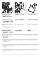
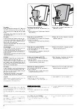
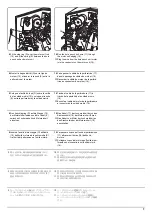
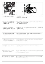
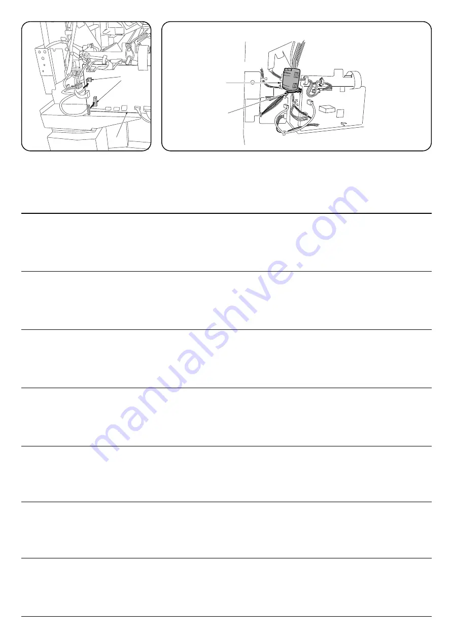
15.
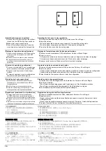
Plug the 2 punch PWB wires into the con-
nectors (27) on the DF main PWB (26).
16.
Install the small clamp (K) on the finisher, then pass and fasten the wires from the motor unit and
hole punch unit.
17.
Attach the ferrite core (M) to the wire.
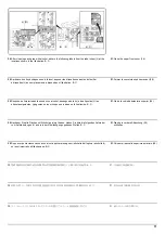
15.
Raccorder les 2 câbles de la PWB de la per-
foratrice aux connecteurs (27) de la PWB
principale du DF (26).
16.
Monter le petit collier (K) sur le retoucheur puis faire passer les câbles du moteur et de la perfora-
trice dans ce collier pour les fixer en place
17.
Fixer le noyau en ferrite (M) au câble.
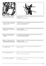
15.
Enchufe los 2 cables del PWB de per-
foración a los conectores (27) del PWB prin-
cipal del DF (26).
16.
Instale el sujetador pequeño (K) en el finalizador, después tienda y ajuste los cables de la unidad
motriz y la perforadora.
17.
Fije el núcleo de ferrita (M) al cable.
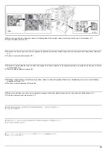
15.
Die 2 Kabel der Locher-PWB an die Steck-
verbinder (27) der DF-Haupt-PWB (26)
anschließen.
16.
Die kleine Klemme (K) am Finisher anbringen, dann die Kabel von der Motoreinheit und der
Lochereinheit hindurchführen und befestigen.
17.
Den Ferritkern (M) am Kabel befestigen.
15.
Collegare i 2 cavi della scheda a circuiti
stampati di perforazione nei connettori (27)
sulla scheda principale PWB (26) della DF.
16.
Installare il morsetto piccolo (K) sul finitore, e quindi passare e fissare i cavi dall’unità motore e
dall’unità di perforazione.
17.
Applicare il nucleo in ferrite (M) al cavo.
15.
パンチ基板の電線 2 本を DF 主回路基板
(26) のコネクター(27) に接続する。
16.
クランプ小(K)をフィニッシャーに取り付け、モーターユニットとパンチユニットからの電線を
通し、
固定する。
17.
フェライトコア(M)
を電線に取り付ける。
15.
将打孔电路板的 2 根电线与 DF 主电路板
(26) 的接插件 (27) 连接。
16.
把小固定夹(K)安装在装订器上,从电机单元和打孔单元出来的导线穿过固定夹来固定。
17.
用磁环(M)套住导线。
15.
펀치기판의 전선 2 선을 DF 주 회로기판
(26) 의 커넥터 (27) 에 접속합니다 .
16.
클램프 소(K)를 피니셔에 장착 , 모터 유니트와 펀치 유니트에서부터 전선을 통과시키고 고정합
니다 .
17.
페라이트 코어(M)를 전선으로 장착합니다 .
Summary of Contents for UTAX AK 730
Page 5: ...This page is intentionally left blank ...
Page 11: ...This page is intentionally left blank ...
Page 15: ...3NB 3ND 3N0 3NK This page is intentionally left blank ...
Page 25: ...3NB 3ND 3N0 3NK 1 1 10 This page is intentionally left blank ...
Page 43: ...3NB 3ND 3N0 3NK 1 2 18 3 Remove tape and pad Figure 1 2 23 Tape Pad ...
Page 45: ...3NB 3ND 3N0 3NK 1 2 20 This page is intentionally left blank ...
Page 81: ...3NB 3ND 3N0 3NK 1 3 36 This page is intentionally left blank ...
Page 157: ...3NB 3ND 3N0 3NK 1 4 76 This page is intentionally left blank ...
Page 169: ...3NB 3ND 3N0 3NK 1 5 12 This page is intentionally left blank ...
Page 206: ...3NB 3ND 3N0 3NK 2 2 11 This page is intentionally left blank ...
Page 246: ...1 1 INSTALLATION GUIDE INSTALLATION GUIDE FOR 4000 SHEETS FINISHER ...
Page 269: ...INSTALLATION GUIDE FOR FINISHER ATTACHMENT KIT MFP A ...
Page 283: ...INSTALLATION GUIDE FOR FINISHER ATTACHMENT KIT MFP B ...
Page 284: ...E F A H G I J B D C ...
Page 291: ...INSTALLATION GUIDE FOR FINISHER ATTACHMENT KIT PRINTER ...
Page 295: ...INSTALLATION GUIDE FOR CENTER FOLDING UNIT ...
Page 312: ...INSTALLATION GUIDE FOR MULTI TRAY ...
Page 326: ...INSTALLATION GUIDE FOR MULTI TRAY ATTACHMENT KIT PRINTER ...
Page 330: ...INSTALLATION GUIDE FOR PUNCH UNIT ...

