3PC
2-2-1
2-2 Electrical Parts Layout
2-2-1 Electrical parts layout
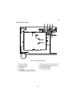
(1) PWB and sensors
Figure 2-2-1 PWB and sensors
1. PF main PWB (PFMPWB) .................... Controls electrical parts.
2. PF paper conveying cover switch
(PFPCCSW).......................................... Breaks the safety circuit when PF paper conveying cover is
opened, and resets paper jam detection.
3. PF paper sensor 1 (PFPS1).................. Detects the presence of paper in cassette 3.
4. PF paper sensor 2 (PFPS2).................. Detects the presence of paper in cassette 4.
5. PF lift sensor 1 (PFLS1)........................ Detects the lifts of cassette 3 reaching the upper limit.
6. PF lift sensor 2 (PFLS2)........................ Detects the lifts of cassette 4 reaching the upper limit.
7. PF feed sensor 1 (PFFS1) .................... Detect paper jams of paper feed section in the cassette 3.
8. PF feed sensor 2 (PFFS2) .................... Detect paper jams of paper feed section in the cassette 4.
9. PF paper gauge sensor 1 upper
(PFPGS1(U))......................................... Detects the paper level in the cassette 3.
10. PF paper gauge sensor 1 lower
(PFPGS1(L)) ......................................... Detects the paper level in the cassette 3.
11. PF paper gauge sensor 2 upper
(PFPGS2(U))......................................... Detects the paper level in the cassette 4.
12. PF paper gauge sensor 2 lower
(PFPGS2(L)) ......................................... Detects the paper level in the cassette 4.
13. PF paper size detection switch 1
(PFSDSW1) .......................................... Detects the size of paper in cassette 3.
17
14
16
12
11
15
13
9
2
4
6
3
5
10
19
18
7
8
1
Machine front
Machine inside
Machine rear
Summary of Contents for Utax PF 810
Page 1: ...Service Manual Paper Feeder PF 810 Rev 2 0 Date 28 07 2014 3PCSM062 ...
Page 2: ...Service Manual Paper Feeder PF 810 Rev 2 0 Date 28 07 2014 3PCSM062 ...
Page 5: ...This page is intentionally left blank ...
Page 11: ...This page is intentionally left blank ...
Page 16: ...3PC 1 1 3 1 1 3 Machine cross section Figure 1 1 2 Paper path ...
Page 17: ...3PC 1 1 4 This page is intentionally left blank ...
Page 27: ...3PC 1 2 10 This page is intentionally left blank ...
Page 62: ...3PC 1 5 3 4 Pull out the right cassette 5 Remove the connector Figure 1 5 3 Connector ...
Page 73: ...3PC 1 5 14 This page is intentionally left blank ...
Page 75: ...3PC 1 6 2 This page is intentionally left blank ...
Page 85: ...3PC 2 2 4 This page is intentionally left blank ...
Page 91: ...3PC 2 3 6 This page is intentionally left blank ...


