SCOOTER
Printed December 1959.
250 c.c. O.H.V. TWIN CYLINDER SCOOTER
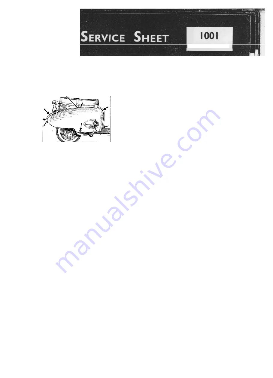
REMOVING THE SIDE VALANCES
To remove the side valances for maintenance on the engine unit, take off
the dual seat by removing the two 1/4 in. nuts and bolts coupling the "C"
shaped hinges to the dual seat brackets.
Take out the three 3/16 in. bolts, two at the front of the valances and one
at the rear bottom end. Then remove the two 1/4 in. diameter nuts and bolts
which secure the number plate.
When a spare wheel and rear carrier are fitted the number plate is on the rear
carrier and need not be removed from the carrier.
Break the connectors to the rear lamp. These will normally be found
underneath the rubber tool tray, but when a rear carrier and spare wheel are
fitted the connectors will be well outside the valances and will be obvious.
When a spare wheel is fitted, undo the two wheel nuts, slacken off the
two bolts at each side of the dual seat that support the rear carrier, lift the
carrier and take off the spare wheel. Then take out the two bolts at the sides of
the dual seat and remove the carrier complete with number plate. Remove the
two 5/16 in, bolts at the middle rear of the valances, which also hold the spare wheel
brackets.
The valances will now only be held by two bolts at each side, one domed
slotted bolt immediately below the dual seat and one round head bolt at the
bottom edge immediately above the pillion passenger's footboards. On the right-
hand side of the machine the dual seat catch knob must also be removed. The
valances are now ready to be taken away complete with the plastic
headings.
Reassembly of the valances is the complete reverse of dismantling.
They should therefore be located first by refitting the two domed head slotted bolts
immediately below the dual seat and the round head bolts above the pillion
passenger's footboards, but these two bolts should be left slack to
facilitate refitting the bolts around the edges of the valances.
It is a wise precaution to locate all the bolts through the beading
before tightening.
(best to locate these in the beading as taken out;
regreased with copper grease IMO)
Summary of Contents for TW2
Page 1: ......
Page 55: ...SERVICE SHEET No 1050 contd Wiring Diagram 6 Volt Model...
Page 57: ......
Page 58: ...i SERVICE SHEET No 1050 contd...
Page 61: ......
Page 66: ......
Page 73: ......
Page 74: ......
Page 75: ......


