SERVICE SHEET No.
1005
(contd.)
We now come to one of the bearings which requires special mention ; this is the gearbox mainshaft and
pinion sleeve bearing which is a special sealed bearing, the seal being outwards, and the rear swinging arm
bearing plate must be refitted before this bearing can be inserted through the gearbox.
Refit the swinging arm bearing plate, which is secured by the four hexagon headed bolts and two
locking plates, turn the locking plates up on to all four bolts after final tightening, press the sealed
bearing in, seal side first, through the gearbox, making sure that it seats right home against the swinging arm
plate. Now press the pinion sleeve through the gearbox and into the bearing and make sure that it is right
home, otherwise when the gearbox cluster is assembled it may tighten up. After pressing the pinion sleeve
right home insert the distance piece over the outside of the pinion sleeve and into the rear swinging arm
bearing plate.
Apply clean engine oil to the crankshaft timing side bearing and insert the crankshaft from the left
hand side, making sure that it is absolutely clean and free from any traces of grit or dust. Be sure that the
dowel is in position on the timing side to locate the timing gear.
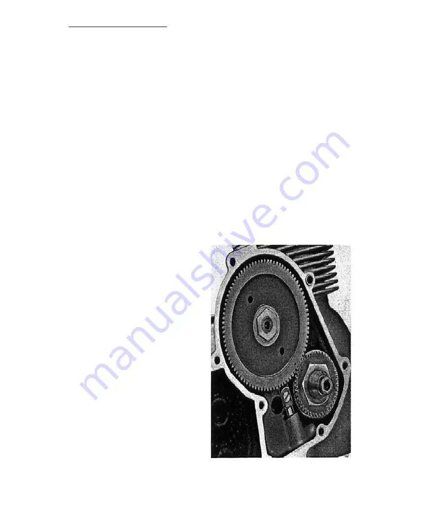
Place the timing gear over the crankshaft so that the keyway is in line with the dowel and the timing
mark on the pinion is on the outside. In this case there is no tab washer used under the nut, but the nut
has a special register which faces towards the pinion. Using service tool 61-5022 hold the crankshaft
and tighten the nut on the pinion.
Now remove the nut which was placed on the camshaft for the
purpose of testing the pump, insert the thrust washer over the
camshaft and against the elongated brass plate, then refit the
camshaft pinion with the timing mark on the outside and meshed
with the timing mark on the crankshaft pinion. The easiest way to
do this is to mesh the camshaft gear with the crankshaft gear and
then to turn the camshaft gently to line its keyway up with the
keyway in the pinion. When both are in line gently tap the pinion
home, place the tab washer in position so that the centre key or
tab is in the keyway on the shaft, screw on the nut and tighten,
finally turning over the tab washer on to one of the flats on the
nut.
It will be assumed that the carbon has been removed from
the pistons, that the rings have been checked for gap, and that the
pistons have been replaced on their connecting rods the correct
way round according to the markings placed inside the skirt when
dismantling.
Apply a coating of clean engine oil to the piston skirt and
rings and to the crank journals, remove the cap from one of the
rods, placing the cap and the nuts in such a position as to
facilitate assembly and ensure correct mating of cap,bolts and
nuts as mentioned in Service Sheet No. 1004 dealing with
dismantling. With service tool 61-5004 compress the rings on
the piston, having first positioned the ring gaps equidistant
round the piston. Lubricate the cylinder wall and insert the big
end of the connecting rod down through the cylinder, being
careful not to scratch the cylinder bore, slide the piston into the
bore and at the same time direct the big end over the crankshaft.
When the big end of the connecting rod is in position replace the
cap ensuring that the numbers on the cap mate up with the
numbers on the rod, place new special tab washers over the bolts
and screw on the nuts until they grip the tab washers, then turn
down the
Fig. 15. Timing pinions.
Summary of Contents for TW2
Page 1: ......
Page 55: ...SERVICE SHEET No 1050 contd Wiring Diagram 6 Volt Model...
Page 57: ......
Page 58: ...i SERVICE SHEET No 1050 contd...
Page 61: ......
Page 66: ......
Page 73: ......
Page 74: ......
Page 75: ......


