8
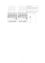
3.2.2.7. Input Port of Limit Signal on Wiring Board
4 roads of limit signal of sensor on wiring board. 2 limit signals input on two side of
each axis. (There are hard limit and origin limit.)
X/Y limit signal input
Port
No.
Title
Explanation
8.X/Y
LIMIT
1
DC24V
24V power supply positive polarity output
2
ELY+
Limit switch on another side that is opposite to origin on
Y axis
3
ELX+
Limit switch on another side that is opposite to origin on
X axis
4
ELY-
Limit switch on the origin on Y axis
5
ELX-
Limit switch on the origin on X axis
6
GND
Grounding output
Z/U limit signal input
Port
No.
Title
Explanation
9.Z/U
LIMIT
1
DC24V
24V power supply positive polarity output
2
ELU+
Limit switch on another side that is opposite to origin on
U axis
3
ELZ+
Limit switch on another side that is opposite to origin on
Z axis
4
ELU-
Limit switch on the origin on U axis
5
ELZ-
Limit switch on the origin on Z axis
6
GND
Grounding output
Wiring diagram:


