background image


ASSEMBLY 

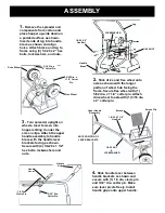
1. 

Remove the spreader and 

components from carton and 
place hopper up-side down on 
a padded surface as shown. 
Insert ends of leg into handle 
brace as shown and align 
holes. Attach brace and leg to 
frame using (4) 1/4-20 x 2” hex 
bolts, lockwashers, and nuts. 
   

3. 

Turn spreader upright on 

wheels. Insert screen into 
hopper sliding it under the  
screen clips. Attach the upper 
handle assembly to handle 
brace with the handle lever 
brackets facing as shown. 
Secure with (4) 1/4-20 x 1 1/2” 
hex bolts, lockwashers and 
nuts. 

2. 

Slide drive and free wheel onto 

axle as shown with the longer 
portion of wheel hub facing the 
frame. Secure free wheel with (1) 
5/32 dia. x 1 1/4” cotter pin. Attach 
drive wheel to axle with (1) 3/16 dia. 
x 2” cotter pin. 

5/32 Dia. x 

1 1/4” Cotter 

Pin 

3/16 Dia. x 

2” Cotter Pin 

NOTE POSITION OF 
 LEVER BRACKETS 

Drive Wheel 

Free Wheel 

Handle  

Brace 

 Leg 

1/4-20 X 2” 

Hex Bolt 

1/4-20 NUT 

Upper Handle 

Assembly 

 Screen 

 Screen Clip 

1/4-20 X 1 1/2” 

Hex Bolt 

1/4-20 NUT 

&  

LOCKWASHER 

LOCKWASHER 

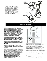
4. 

Slide handle lever between 

handle brackets as shown and 
secure with (1) 1/4 dia. clevis pin 
and 3/32” dia. cotter pin. Make 
sure lever pivots freely. Install 
handle grips onto upper handle. 

 1/4 Dia. 

Clevis Pin 

 3/32” Dia. 
Cotter Pin 

 Handle  

Lever 

 Handle  

Grip 

Summary of Contents for 30 +

Page 1: ...OWNER S MANUAL...

Page 2: ...Slide drive and free wheel onto axle as shown with the longer portion of wheel hub facing the frame Secure free wheel with 1 5 32 dia x 1 1 4 cotter pin Attach drive wheel to axle with 1 3 16 dia x 2...

Page 3: ...rt Close before stopping Always push spreader never pull 4 Hold handle so top of spreader is level Tipping the spreader too far can cause uneven spreading 5 The settings and swath widths on the produc...

Page 4: ...ed example volume in bottle 2 left not equal to bottle 2 right adjust the pattern control as described in the PATTERN ADJUSTMENT section Once the pattern is uniform the effective pattern width can be...

Page 5: ...Settings and Spread Width section of this manual These settings are approximate and may vary due to physical characteristics of the product Walking speed wear condition of the turf and humidity may c...

Page 6: ...r teeth with dry graphite Re install gear cover 5 Gear mesh should be checked on a regular basis during high use periods Clearance between the axle gear and pinion gear should be minimal but not tight...

Page 7: ...lacement of any Product or Product part the replaced item shall become the property of Sherriff Amenity If Sherriff Amenity determines that the Product covered by this warranty requires service Sherri...

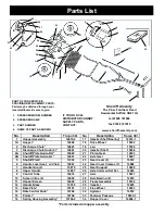
Page 8: ...e Bearing 4 14933 11 Hopper Screen 14603 29 Frame Assembly 15184 12 Handle Brace 15188 30 Impeller 14625 13 Rate Plate 15191 31 Free Wheel 15033 14 Rate Control Knob 12704 32 Agitator 14510 15 Pointer...

Reviews: