11
ASSEMBLY STEPS
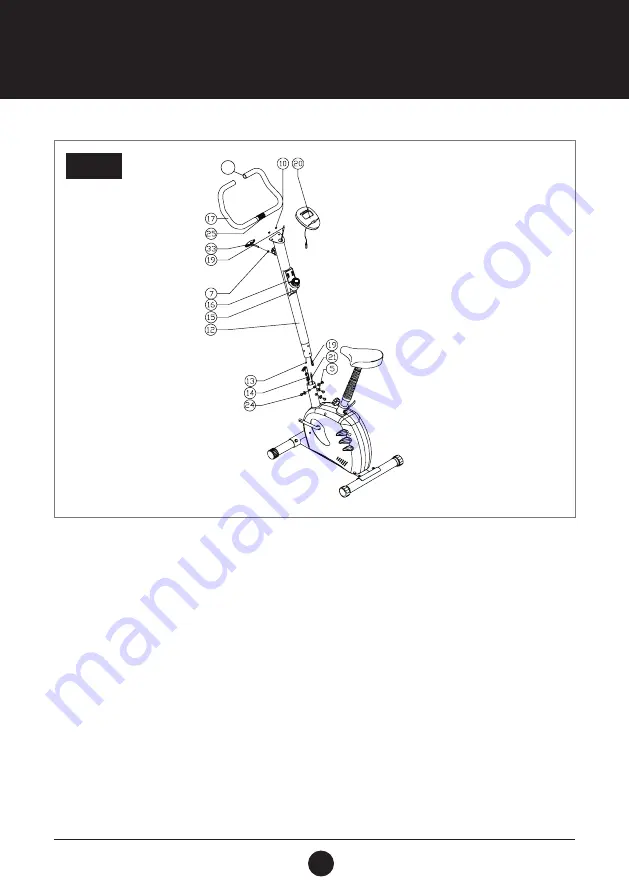
STEP 3:
CONSOLE ASSEMBLY
Remove the Screws (M8 x 12 mm) (24) and Arc Washers (Ø8 x Ø20 x T1.5) (5) from the Main Frame (1).
Connect the 2 ends of the Tension Control Cables (13) and (14). Connect the 2 ends of the Console
Wire (700 mm) (19) and Sensor Wire (650 mm) (21). Slide the Handlebar Post (Ø50 x T1.5 x 640 mm) (12) into
the Main Frame (1) and secure into place using 4 Screws (M8 x 12 mm) (24) and 4 Washers (Ø8 x Ø20 x T1.5) (5)
provided.
Pull the Tension Strap until it is hand tight and lock it into place using the small clasp. Place the
Handlebar (Ø22) (25) into the Handlebar Bracket on the front of Handlebar Post (Ø50 x T 1.5 x 640 mm) (12).
Tighten the T-knob (33) and Washer (Ø8 x 17 x 1.2) (7) to lock the Handlebar (Ø22) (25) into place.
Connect the Console Wire (700 mm) (19) to the Console (KH-8802) (20). Secure the Console (KH-8802) (20)
with 2 Screws (M5 x 12 mm) (10) to the holder on the top of Handlebar Post (Ø50 x T1.5 x 640 mm) (12).
Slide both Foam Grips (17) onto the Handle Bar (Ø22) (25), then insert the 2 End Caps (Ø22) (23 A) into the
Handle Bar (Ø22) (25) ends.
CAUTION
Ensure that cables are not damaged during assembly or when tightening screws.
STEP 3
23A
Summary of Contents for RESPONSE CYCLE 100
Page 8: ...8 EXPLODEDDRAWING...


