10173-14
5. ASSEMBLY STEPS
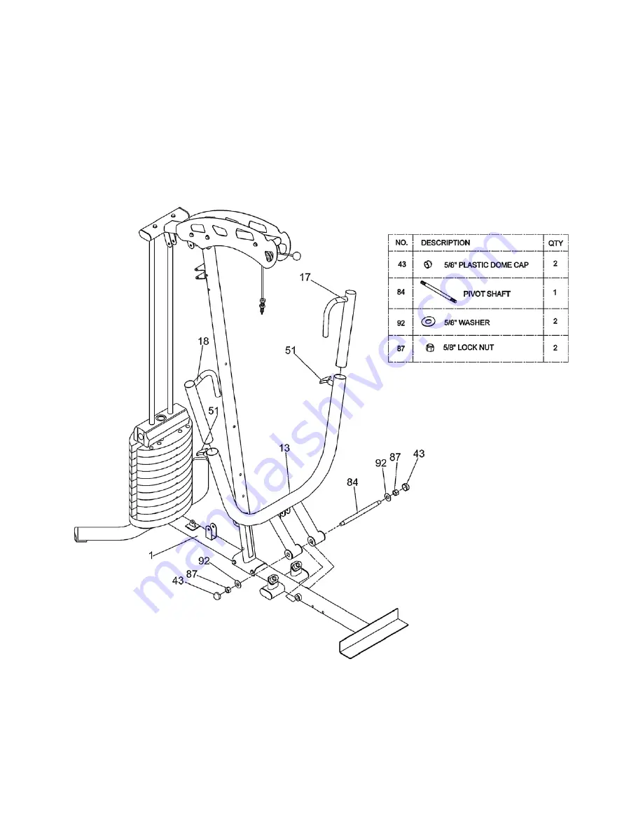
STEP 4
•
Attach Bench Press Arm (13) to the Main Base (1) using one Ø19 x 280mm Pivot Shaft (84), two 5/8” Washers (92), two
5/8”Lock Nuts (87) and two 5/8” Plastic Dome Caps (43).
•
Insert both Adjustable Press Frames A&B (17, 18) into the Bench Press Arm (13) using two PT-1B Pop Pins (51) as shown.
Summary of Contents for VISION 350
Page 6: ...10173 6 3 HARDWARE LIST...
Page 7: ...10173 7 3 HARDWARE LIST...
Page 8: ...10173 8 3 HARDWARE LIST...
Page 20: ...10173 20 Step 9 5 ASSEMBLY STEPS...
Page 29: ...10173 29 11 EXPLODED DRAWING...


