1
1480-6
4. ASSEMBLY STEPS
STEP 01
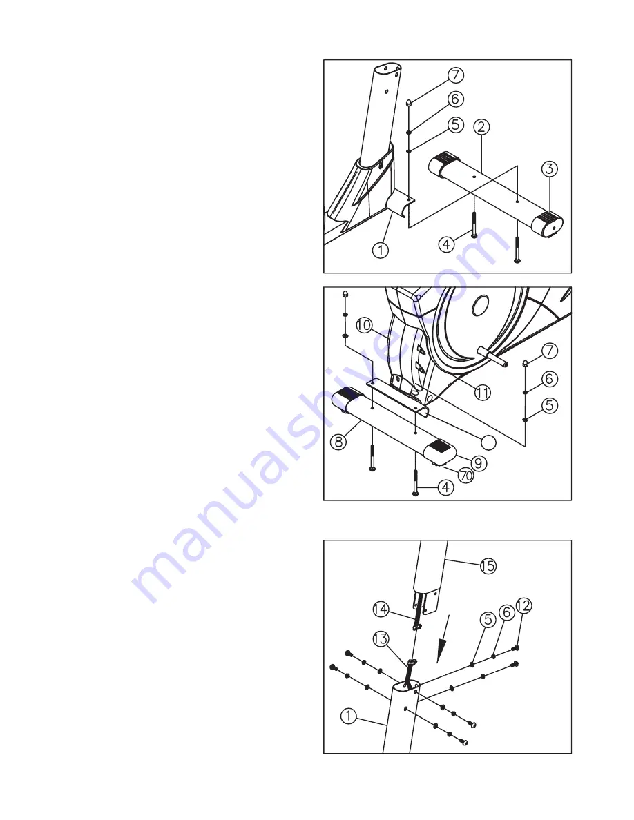
Attach The Stabilizer
s!TTACHTHE&RONT3TABILIZER ASSEMBLEDWITHTWO
Front Wheel Caps (3) to Main Frame (1), using two
Carriage Bolts (4), two Washers (5), two Spring Washers
(6), and two Cap Nuts(7).
s!TTACHTHE2EAR3TABILIZER ASSEMBLEDWITHTWO2EAR
Foot Covers (9) to Main Frame (1), using two Carriage
Bolts (4), two Washers (5), two Spring Washers (6), two
Cap Nuts (7).
s5SETHEADJUSTABLESCREWS TOLEVELTHEELLIPTICAL
STEP 02
Attach The Handlebar Post (15) and
Computer Cables (13 and 14)
s(OLDTHE(ANDLE"AR0OST THENCONNECTTHETWO
ends of Computer Cable (13) and (14). When
the electrical cable is connected, push the Handlebar
Post (15) into the Main Frame (I)
s)NSERTONE3PRING7ASHER ANDONE7ASHER ON
each Bolt (12).
s)NSERT"OLTS INTOTHEHOLESOF-AIN&RAME AS
depicted.
CAUTION:
Ensure that cables are not damaged
during assembly or when tightening screws.
Summary of Contents for X-TRAINER 400
Page 20: ...1480 20 10 EXPLODED DRAWING...
Page 21: ...1480 21 EXPLODED DRAWING...


