1480-9
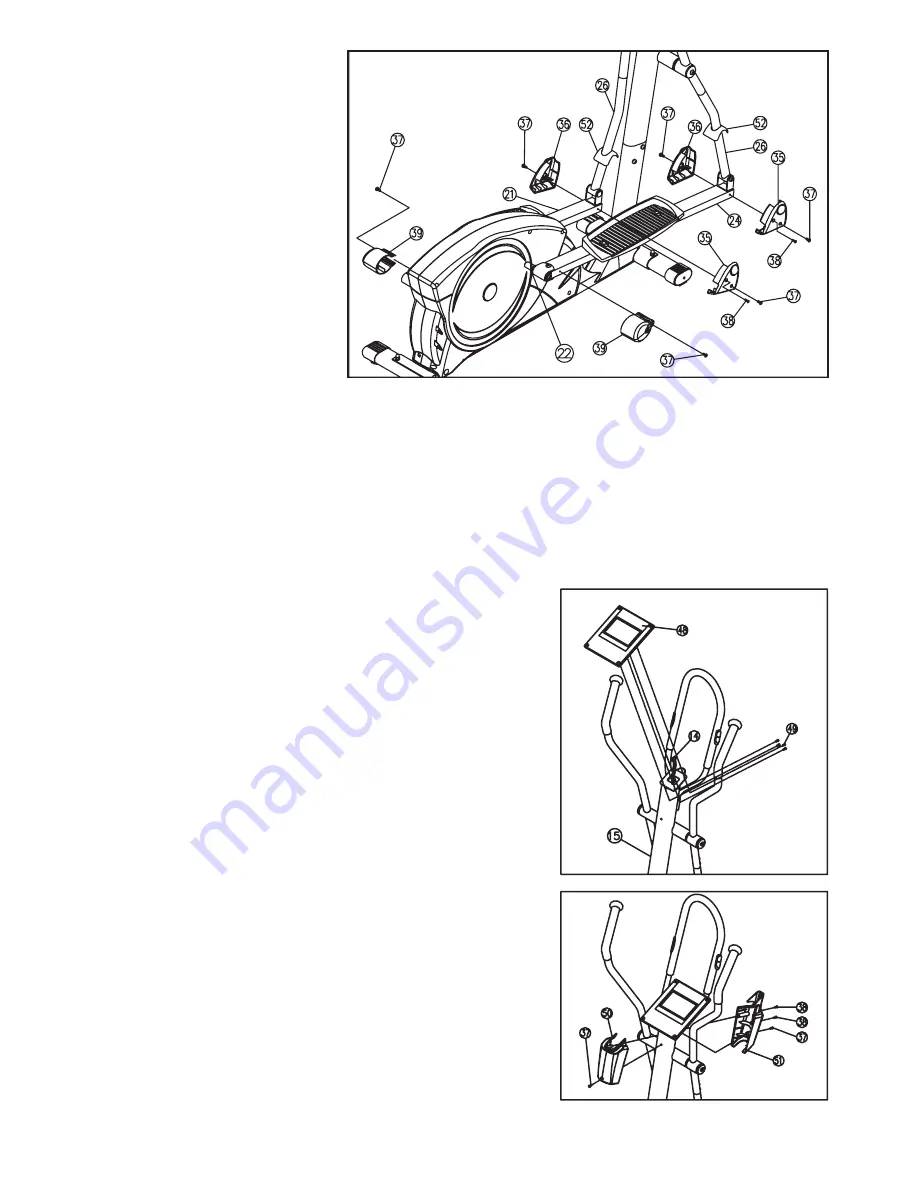
STEP 07
Installation of the Front and
Rear Pedal Cover
(35, 36 and 39) on the
Pedal Tubes (21and 24).
s0USHTHE2EAR0EDAL4UBE#OVER ONTOTHECONNECTIONPOINTOF#ROSS&RAME AND0EDAL4UBEAND AND
fasten it with Screw (37).
s0UTEACHOFTHE,EFTAND2IGHT0EDAL&RONT#OVERAND ONTOEACHCONNECTIONPOINTOF3WIVEL4UBE AND
Pedal Tubes (21and 24) together and fasten them with Screws (37 and 38).
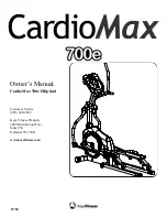
STEP 08
Installation of The Computer (48) and Handle Bar Cover (50
and 51) on The Handlebar Post (15).
s
Plug the ends of Computer Cable (14) and Pulse Cable (40) into the
socket at the backside of the Computer Console(48).
s0LACETHE#OMPUTER#ONSOLE ONTOTHEPLATEATTHEUPPERENDOF
the Handlebar Post (15) and fastenwith 4 Screws (49)
(Note: When placing the computer, thread the cables in
the holes of the handlebar post (15) so that the cables
cannot be trapped or damaged)
s0UTTHE&RONTAND"ACK(ANDLEBAR#OVERAND ONTOTHEUPPER
end of Handlebar Post (15) together and fasten them with Screws (37
and 38).
Summary of Contents for X-TRAINER 400
Page 20: ...1480 20 10 EXPLODED DRAWING...
Page 21: ...1480 21 EXPLODED DRAWING...


