background image


T3-OPX user guide 


Version 1.2 


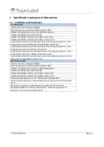
Summary of Contents for T3-OPX

Page 1: ...T3 OPX user guide Version 1 2...

Page 2: ...1 General description 9 1 5 2 The machine s purpose and intended use 9 1 5 3 Warning about foreseeable misuse 9 1 5 4 Specifications T3 OPX 10 1 5 5 Specifications MailTable 1 MT1 13 1 5 6 Specificat...

Page 3: ...2 Settings menu 38 4 2 1 Consumables Button 38 4 2 2 Network Button 39 4 2 3 Updater Button 40 4 2 4 User Preferences Button 40 4 2 5 User Management button 41 4 2 6 Printing prefrences button 42 4 3...

Page 4: ...calibrating the job media height 63 9 Printing on uneven surfaces die to die overlap feature 65 10 Edge sensor TOF control 66 10 1 Sensor overview 67 10 2 Adjusting the sensor to the media 67 11 User...

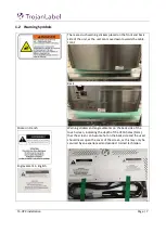
Page 5: ...T3 OPX installation Page 4...

Page 6: ...d 2 Audio Video Information and Communication Technology Equipment Part 1 Safety Requirements IEC 62368 1 2014 Ed 2 C1 C2 Audio Video Information and Communication Technology Equipment Safety Requirem...

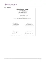
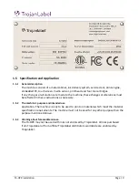
Page 7: ...T3 OPX installation Page 6 1 1 1 Emissions...

Page 8: ...s the table Front Back Sticker in French Engravement in English Warning stickers and engravements on the back side of the touch screen indicating the depth of the VESA holes 5mm that the screen can be...

Page 9: ...mployer the owner of the machine to ensure that anyone who is to operate service maintain or repair the machine have read the instructions As a minimum they should have read the part s relevant for th...

Page 10: ...ions must be reflected in these instructions as necessary 1 5 2 The machine s purpose and intended use Application The machine is only to be used to print on materials which meet the material specific...

Page 11: ...nmental Physical Printer operation Operation 20 to 30 C 59 to 86 F Transport 40 to 60 C 40 to 140 F Relative humidity 20 to 80 Altitude 0 to 3048 m Power requirements 100 240V AC 50 60 9A power supply...

Page 12: ...r Card board paper board wooden boards paper bags Most porous materials Width Depends on transport installation 600mm Trojan standard table 1000mm Trojan wide table Supported image lengths 25 4 mm 914...

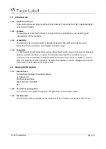
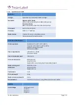
Page 13: ...T3 OPX installation Page 12...

Page 14: ...ps 27m min Power requirements 100 240V AC 50 60 Hz 2 5A power supply Dimensions Width 626 mm incl Emergency stop button Length 1507 mm Height From 892 mm to 595 mm Support material width 600 mm Weight...

Page 15: ...to 18 ips 27m min Power requirements 100 240V AC 50 60 Hz 2 5A power supply Dimensions Width 1026 mm incl Emergency stop Length 2007 mm Height From 890 mm to 590 mm 5 positions Support material width...

Page 16: ...allation Page 15 2 T3 OPX physical overview This is example 2 1 Front side Edge Sensor Adjustable legs Touch Screen Feeder table optional Media Guides Vacuum unit optional Table emergency stop Catch t...

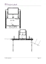
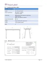
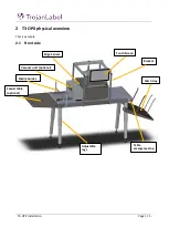
Page 17: ...T3 OPX installation Page 16 2 2 Backside Height controllers 3 Inlets Ink lid Serial plate...

Page 18: ...Inlets detail 2 4 Bottom Power inlet IO serial port fx for feeder Encoder serial port Table communication port Network ethernet USB port Pressure plate area that is used to detect the media height Cra...

Page 19: ...2 6 Media exit side Aerosol filter Replaceable filter Front plate Removeable to access print head area Top lid Access to electronic components Edge Sensor Knobs to move sensor Edge sensor reflective l...

Page 20: ...T3 OPX installation Page 19...

Page 21: ...les separates them MT1 is 600mm wide and 1500mm long excluding feeder and catch trays MT2 is 1000mm wide and 2000mm long excluding feeder and catch trays The image below shows the T3 OPX installed on...

Page 22: ...ide tables 3 Allen key set 2 5 6mm 4 C clip pliers 3 3 MailTable 1 or 2 setup The process for the mailtable 1 and 2 is identical 1 Place the table upside down a Place it on a mat or similar to protect...

Page 23: ...eps using the screws to lock the position 4 Turn over the table on its feet 3 4 T3 OPX Bracket system installation process 1 Mount side brackets on both table sides a Use 2x2 slot knots that are in th...

Page 24: ...tre the brackets 400mm from the emergency stop button plate 2 Mount bracket system on the conveyor table a Install the 4 corner posts loosely i Do not tighten too much as they will need to be adjust t...

Page 25: ...a box surface that will raise the unit 25 35 mm under the bracket system a Using a raises surface will make it easier to fit the actuators to the top bracket system b Examples of raising the OPX unit...

Page 26: ...actuators on the T3 OPX unit a Push each actuator into place in the corresponding black plastic holder closest to where the actuator cable enters the unit Touch screen mouse connection notice the RED...

Page 27: ...e the rotation of the actuator The motor should be facing inwards and the hole at the bottom of the actuator should line up with the black plastic mount c Secure the actuator by pushing in the pin and...

Page 28: ...be some resistance pushig it through the plastic fitting at the top d Screw the metal rod in place i Depending on the padded sureface the system is resting on the metal rod will most likely hover a bi...

Page 29: ...9 Mount the lid on the OPX 3 5 Connect encoder and table controls Trojan MT1 and MT2 Prerequisites 2 x serial cables included with the table 1 Connect the encoder serial cable 2 Connect the table comm...

Page 30: ...nnect the power supply cord to the printer power inlet a See 2 3 Inlets detail for location 2 Connect the power supply cord plug to the power source outlet grounded wall or extension cables 3 Connect...

Page 31: ...ower inlet switch on both T3 OPX and mail table MT1 2 3 10 Calibrate the table position and level unit Calibrate the table position for the unit to determine the zero height position of the table and...

Page 32: ...the ink needles inside the printer Repeat this step for each color 4 Close the ink door 5 Confirm that the inks are recognized in the status bar on the touch screen Below is just an example 3 12 Purg...

Page 33: ...will require the spittoon placed under the print head After pressing OK print unit will be moved to the purge height and purge will start on next power on The operation can not be undone once accepted...

Page 34: ...T3 OPX installation Page 33 i The process will use the purge height in the settings menu...

Page 35: ...rate the nozzles and ink drop based scans Overview of the Dianosticsa menu Prerequisites 1 x scanner EPSON v600 High grade ColorLok paper Minimum A4 160 grs or heavier o ColorLok logo Print height is...

Page 36: ...o the diagnostics main menu b If not i Reprint go to step 5 Press Scan the nozzle alignment chart 6 Set Die to die overlap to 0 a This feature is explained in chapter 9 Printing on uneven surfaces die...

Page 37: ...state of the nozzles and will show which once that are not printing Scanning the printed output will enable the printer to some extend cover the missing nozzles However please note that there a no gu...

Page 38: ...on Page 37 4 General Settings HOME tab 4 1 Overview menu Information from currently printed job including Preview image of the label which is being printed at the moment Label counter Name of print jo...

Page 39: ...umber of the Trojan Control interface GUI currently running on the machine Trojanlabel technicians or the local Trojanlabel distributor complete the owner and distributor contact information field at...

Page 40: ...sts This is for display only no conversions are made based on the input IMPORTANT Press the blue Save button to apply the changes 4 2 2 Network Button Select Use DHCP checkbox to acquire IP address fo...

Page 41: ...to apply selected language Save printed jobs to job library Enabled The print job is stored and available for reprinting from the job library Disabled The print jobs sent after disabling this option a...

Page 42: ...r authentication Enable user management checkbox When selected and activated then user authentication is required for accessing specific functions in TrojanControl software A user with User Management...

Page 43: ...first in first out system The queue can be managed from Print queue menu see section 11 3 5 Paused The print queue is paused when machine starts Normal mode job default speed IPS defines the default s...

Page 44: ...ink tank price and print head price given at HOME Settings Consumables menu Print head cost is added Cost label ink PH media calculation is the cost 1 label in the actual print job based on ink tank...

Page 45: ...d Total statistics and history for all the print heads which have been inserted into the T3 OPX All print unit serial numbers will be registered and statistics for each printhead can be compared NOTE...

Page 46: ...int quality defects Shutdown process may take 1 2 minutes Shuts down the T3 OPX completely NOTE When shutting down the unit it is advised to wait with turning the power switch off until the shutdown p...

Page 47: ...he T3 OPX can be set or acquired at from HOME Settings Network menu Current IP address displayed at HOME Settings Network menu NOTE IP address on screenshot above is an example only Actual IP address...

Page 48: ...T3 OPX installation Page 47 Closer view NOTE Ink consumption is more detailed in this view and displayed for each used base color CMYK and in total as well...

Page 49: ...is running Note the server does not have to run on the same PC as the client This can be done two ways on the RIP server PC 1 Click the start menu open Navigator then click Navigator Server 2 Double c...

Page 50: ...EDITS screen is opened In this screen you can make various changes such as rotations print range collation etc a You can also select the FULL JOB EDITOR at the top right 5 In the Full Job Editor scre...

Page 51: ...t 5 2 2 Rotation offsetting and media size To use the offsetting moving and rotation it is important that the Media size is adjusted to fit the new dimensions When a job is loaded the media size will...

Page 52: ...Rotation Rotation is done using the rotation button Below is an example of the pizza artwork being rotated If settings are set to original will rotation be possible without having to modify the media...

Page 53: ...naged in the language settings of the PC It is not possible to use the offset button to move the media without adjusting the media size too Unless you just want to truncate the artwork as this is what...

Page 54: ...ator client it is placed on the Navigator folder in the start menu 3 Right click the DFE workflow should be the only one and select Edit Workflow 4 Go to the XiPosition blue circle 5 Set the width and...

Page 55: ...8 Automatically calibrating the job media height This will ensure that the job has the correct print height relative to the media and edge sensor is set 2 Place the media to print on the feeding side...

Page 56: ...int on such as pre setting the height of the media and where the artwork is positioned on the media i e the TOF Top of form i e the distance from the leading edge of the media Media profiles are creat...

Page 57: ...ements of 0 2 mm Enter a value and the unit will move to the position 7 1 3 MailTable MT1 2 controls 7 1 3 1 Conveyor speed MT1 and MT2 controls Move the table belts forward or backward each push will...

Page 58: ...height controllers The emergency stop can be released by twisting the emergency stop button 7 2 Maintenance overview The maintenance menu controls the print head maintenance functions which includes c...

Page 59: ...vice tray button and wait for the service tray to retract Pull out the service tray and replace it with a fresh tray Notice the print head will be uncapped during this process so have the replacement...

Page 60: ...relative to the detected edge of the media The Media settings has a profile control section and three tabs to manage the properties of the selected profile 7 3 1 Profile control section Save Apply Sav...

Page 61: ...s o The print unit is not physically moved until the apply settings button is pressed Auto height adjustment The auto adjustment will use the weight specified in the Force setting below to apply press...

Page 62: ...arton 200 Envelope 1000 7 3 3 Advanced tab Tilt X mm Set the tilt across the printhead in millimeters 5mm Useful if the material is slightly higher in one of the sides fx bag handles Tilt Y mm Set the...

Page 63: ...ed use the start and stop button to test the fan settings in Zone 1 5 These settings are then saved to the media profile and used when printing with profile 7 3 5 Setting up a media job profile in Med...

Page 64: ...ght to ensure that the print engine is placed high enough for the media to enter the print zone under print unit b Move the media under the edge sensor either i Manually or ii Place it on the feeding...

Page 65: ...Controllers will move up to 20mm when pressing the Move and Adjust Height button if the current print height is physically less than 20mm 2 Setting the force too high can crush the material 3 If t he...

Page 66: ...values should be used when darker lines appear too close to the media The die to to overlap feature allows the operator to control the die lines that are positioned with approximately 20mm separation...

Page 67: ...refore not a part of the Media Profile in media settings Consequently adjusting the die to die overlap will affect all media profiles 10 Edge sensor TOF control The edge sensor is used to detect the e...

Page 68: ...uttons 9 and 10 to adjust the value Remember that the sensor should not be over the belts but over the black surface on the table 3 Place the media under the sensor the Led indicator 7 should light up...

Page 69: ...sure the unit is not printing 3 Go to the T3 OPX tab 4 Select Maintenance 5 Press Remove Service Tray 6 Open the service door on the feeding side of the unit by removing the four finger screws This pr...

Page 70: ...it stops The gas pumps will maintain the position a It can carry the weight of the optional Vacuum unit 8 Wait for the service tray to be pushed to the end 9 Pull the service tray out 10 Install the...

Page 71: ...the back side of the unit 2 There is a hole under the ink doors 3 Insert the Torx screwdriver and locate the service tray screw should be straight in Warning Moving the service tray will uncap the pri...

Page 72: ...articles that is not absorbed by the media when printing Although the filter is effective some particles will still end up in the print zone on the print head table and side walls The filter can be re...

Page 73: ...tallation Page 72 11 4 1 Aerosol filter replacement process 1 Remove the aerosol filter drawer by pulling the handle 2 Remove the filter in the drawer 3 Insert a fresh filter 4 Insert the aerosol filt...

Page 74: ...ed to use the default directories when prompted for location d Type in the ip address of the T3 OPX when prompted for it i To find the ip address see chapter 4 2 Settings menu 4 After the installation...

Page 75: ...o to HOME Settings Network 2 Click on the Xitron tab a Insert the IP address of the RIP server 12 2 Installing just the client To install just a client on a PC in the same network as the RIP server an...

Page 76: ...e 75 13 Debugging connections 1 To debug the webpath board Connect an external PC to the T1030 board the new webpath a Use a USB USB Mini to connect 2 To the MPCA to a an external PC to the MPCA a Use...

Page 77: ...tilt etc Calibrate the table position height and x nad y tilt to create the base settings calall Read the power state of the mpca Mpcap It will return 1 if the power is on Push the virtual power butt...

Page 78: ...llation Page 77 14 Revision history 1 Thomas Jensen 1 1 Thomas Jensen Add RIP ip address 12 1 and die to die overlap feature 9 1 2 Thomas Jensen RIP Rotation and offsetting explained Manual service tr...

Reviews: