background image

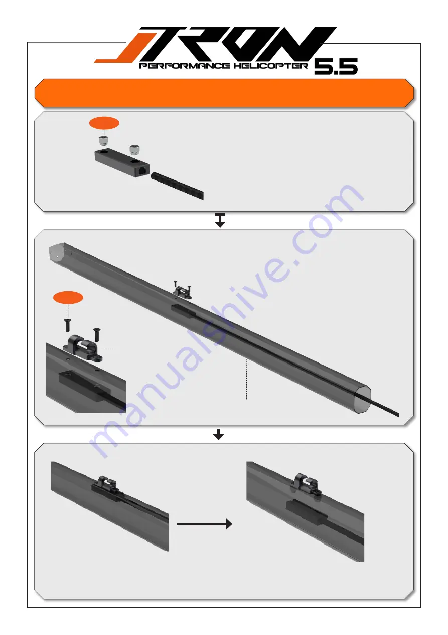
Insert nuts into the tail pushrod mounting device. Use the same direction as 

shown in the illustration.

Use the tail pushrod temporary.

Insert the tail push rod with the nuts facing up into the boom.

Make sure that when you tighten the screws for the tail push rod guide, 

your mounting device facing up like shown in the illustration.

Pull the mounting device out from the nuts.

Tighten the screws.

1.1

3.8

TR501-656 Tail boom for 550mm Blade length 

Tron 5.5 including tail push guide.

TR503-216 Tail pushrod 

guide. Include screw and nut 

for assembling.

Tail assembly.

20

You will need:

A little bit of patience, when doing it for the first time 


Summary of Contents for Tron 5.5

Page 1: ...MANUAL V 1 1 1 ...

Page 2: ...Tail assembly 23 Servos preparation 24 Battery tray 25 28 Upper main frame assembly 29 Motor mount and pinion 30 Servo frame and motor support 31 32 Upper and lower main frame assembly 33 36 Landing gear servos electronic assembly and wiring 37 39 Main drive and head to frame assembly 40 Tail boom to main frame assembly 40 43 Final setup canopy and pre flight check 2 Index ...

Page 3: ... batteries Investigate the reason and fix the problem Do not operate the model again as long as the problem is not solved as this may lead to further trouble and unforeseen accidents In order to prevent accidents and personal injury be sure to observe the following Before flying the helicopter ensure that all screws are tightened A single loose screw may cause a major accident Replace all broken o...

Page 4: ...0kv for 6s 5mm shaft and 6mm shaft diameter 14T 5mm included Octa boom design with oval side shapes no boom supports needed Capable of using a wide range of lipos 6 8 10 or even 12S 6S 5000mAh to 5500mAh recommended Well engineered servo layout in conjunction with the FBL system and ESC Easy cable routing with various options to ensure a clean setup Modern sporty and functional design High visibil...

Page 5: ... 5 with a wide variety of motors and battery setups ranging from 4020 and 4025 motors as well as 6s 8s and even 12s power systems Low head speed and high head speed provide pilots the flexibility they want in a helicop ter to meet the performance they want No matter your needs as a pilot the Tron 5 5 will meet them all 5 CAUTION This radio controlled helicopter is not a toy The product is not suit...

Page 6: ... component epoxy Loctite 243 medium strength Grease 2 Wrench for tail shaft nut Hex screwdriver 1 5mm 2mm 2 5mm 4mm 5mm TR501 518 Pair of customized nut wrench for tail shaft assembly Optionally available at your Dealer ...

Page 7: ...quired 3 midi size servos for swashplate 1 midi or full size servo for tail BL motor 4020 4025 size 5mm or 6mm shaft diameter with min 22mm length ESC 6S 12S 100A 155A FBL device and receiver with 6 channel transmitter ...

Page 8: ...K IV 1060 kv 5 or 6mm shaft SCORPION HK IV 1320 kv 5 or 6mm shaft Recommendation for Tron 5 5 if you use SCORPION equipment YGE 135 LVT ESC YGE AUREUS 135 HVT ESC HOBBYWING PLATINUM PRO 120A V4 HOBBYWING PLATINUM PRO 130A V4 XNOVA 4020 1200 kv LIGHTING OR PER FORMANCE series 5 or 6mm shaft XNOVA 4020 1350 kv LIGHTING 5 or 6mm shaft XNOVA 4025 1120 kv LIGHTING 5 or 6mm shaft Recommendation for Tron...

Page 9: ...Main blade recommendation for Tron 5 5 545mm 560mm length Tail blade recommendation for Tron 5 5 85mm 95mm length 9 We do recommend to use quality connectors for a safe and solid running setup ESC and battery Supra X Pro S6 RCPROPLUS Pro D6 Supra X ...

Page 10: ...10 Screws and nuts ...

Page 11: ...11 Shims and washers ...

Page 12: ...e TR550 804 Main grip bearings set with thrust bearings and shims TR550 110 Pivot steel ball set for head TR550 001 Center Hub 70 shore dampeners included TR504 890 Head dampeners 90 shore for high rpm and hard 3D flying style optional TR550 003 Main grip arms TR550 002 Main blade grip with bearings 1 6 3 6 6 2 5 8 Pay attention to the orientation of the ball cage 12 You will need Loctite 243 blue...

Page 13: ...set and spacers for anti rotation arms TR504 100 Plastic ball link set 2 5mm 5 1 TR550 105 Anti rotation arm set with bearings shims scews and ball links 2 6 Do not tighten now Do not tighten now 13 Important note The ball links have a larger and a smaller diameter Always make sure the larger dia meter is pointing towards the pivot ball when assembling ...

Page 14: ...R550 008 Complete swashplate assembly 1 4 TR550 110 Pivot steel ball set for head 16pcs Swashplate is preassembled in factory Please use loctite 243 on 1 2 and 1 4 Head assembly You will need Loctite 243 blue 14 ...

Page 15: ...230 Servos to swash plate linkage rod set 2 5mm 2 7 3 9 2 4 TR502 104 Hollow main shaft 1 Insert main shaft into center hub first 2 Tighten screw 2 7 3 Tighten screw 2 6 left and right step by step use loctite 248 Make sure the shim 5 1 do not fall out 12mm Head assembly You will need Loctite 243 blue 15 CW tread Important note The ball links have a larger and a smaller diameter Always make sure t...

Page 16: ...3 blue Tail assembly 1 7 1 2 TR550 403 Tail case assembly including bearings TR501 408 Tail pitch arm support TR550 316 Tail pitch arm assembly 5 5 TR550 110 Pivot steel ball set for head 16pcs TR506 511 Tail case bearings 16 ...

Page 17: ... 324 Tail blade holder spindle TR550 110 Pivot steel ball set for head 16pcs 5 6 Internal hole bigger Apply grease Pay attention to the orientation of the ball cage TR506 491 Tail blade holder thrust bearing set TR550 401 Tail blade holder bearing set 17 You will need Loctite 243 blue Grease yellow ...

Page 18: ...TR550 525 Tail blade holder set complete TR550 428 Tail pitch slider assembly complete TR550 322 Tail pitch linkage with c clips and shafts 18 Wrench size for nut 5 5mm Outer diameter should not exceed 9 2mm and min 20mm length is required Optional TR 501518 ...

Page 19: ...ionally TR501 320 Tail pulley 20T optionally 1 2 TR550 405 Tail case belt pulley assemble Pay attention to the orientation of the flat spots on the tail shaft when tight ern the set screws Use a minimal amount of loctite 248 for the setscrews TR506 511 Tail case bearings 19 Screws are loctited by factory Important note The ball links have a larger and a smaller diameter Always make sure the larger...

Page 20: ... you tighten the screws for the tail push rod guide your mounting device facing up like shown in the illustration Pull the mounting device out from the nuts Tighten the screws 1 1 3 8 TR501 656 Tail boom for 550mm Blade length Tron 5 5 including tail push guide TR503 216 Tail pushrod guide Include screw and nut for assembling Tail assembly 20 You will need A little bit of patience when doing it fo...

Page 21: ...ush rod and the shell on the outside of the rood This way you add double safety and the tread can not turn if you adjust the ball link after the assembly is complete hardened Use 2 component epoxy 13mm 3 2 TR550 513 Tail pushrod assembly TR504 100 Plastic ball link set 2 5mm 21 ...

Page 22: ... You will need Loctite 243 blue Insert the tail belt in to the boom 1 9 For best tail authority performance adjust center position of your FBL controller tail servo same as shown in the illustration 90 degree 22 2 0 ...

Page 23: ... midi size 15mm 15mm 15 17mm TR550 112 Pivot steel ball set for servo horns Tail servo recommendation for Tron 5 5 1 full size MKS KST BK HIGHEST Futaba 3 7 23 TR550 112 Pivot steel ball set for servo horns 3 7 Tail servo recommendation for Tron 5 5 1 midi size TR550 112 Pivot steel ball set for servo horns 3 7 ...

Page 24: ...mina 5000mah 6S Gens Ace 5000mah 6S Pulse 5000mah Battery recommendation for Tron 5 5 We experienced the best power versus weight balance with 6S 5000 5500mah size Battery tray You will need Loctite 243 blue TR550 711 Battery tray assembly 24 1 1 ...

Page 25: ...embly You will need Loctite 243 blue 1 1 1 1 TR505 214 ESC carbon tray TR501 200 Tray mounting spacers TR505 211 FBL unit carbon mounting trays TR505 211 FBL unit carbon mounting trays TR501 512 Tail boom clamp set 25 1 1 ...

Page 26: ...e 1 8 2 1 TR503 215 Rail guide for battery tray TR505 102 Upper left frame for midi size tail servo 1 8 TR501 125 Front canopy mounts TR501 118 Rear canopy mounts TR505 106 Breakaway plates 26 2 1 1 8 Upper main frame assembly 4 1 ...

Page 27: ...ssembly TR501 102 Black anodized washers 2 5mm x 8 TR501 122 Servo mount plates TR550 402 Tail idler pulleys with bearings TR550 373 Bearing set and spacers for tail idler pulley You will need Loctite 243 blue TR501 219 Frame spacers 27 Upper main frame assembly ...

Page 28: ... Servo mount plates TR550 420 Release knop for battery tray pre assembled by factory TR501 102 Black anodized washers 2 5mm x 8 TR505 101 Upper right frame for standard tail servo TR503 215 Rail guide for battery tray 1 6 28 Upper main frame assembly ...

Page 29: ...l need Loctite 243 blue 13T 5mm 6mm 14T 5mm 6mm 15T 5mm 6mm 16T 5mm 6mm 17T 5mm 6mm Available pinions for Tron 5 5 3 4 2 2 TR502 014 Motor Pinion 14T 5mm included in kit BL motor 4020 4025 size not included 29 TR501 101 Black anodized washers 3mm x 8 TR506 805 Motor support bearing set ...

Page 30: ...pport with bearings 1 5 TR501 203 Servo mount unit TR501 203 Servo mount unit If you experience that your servo horn will slightly touch the screw head use 1 8 type screws 2 1 2 3 TR501 101 Black anodized washers 3mm TR501 378 Motor mount support 30 2 2 TR506 105 Main shaft bearing set ...

Page 31: ...need Locktite 243 blue TR501 219 Frame spacers 5 Frame spacer will be used for assembling the upper with the lower frame departed by the plastic breakaway frame spacers as shown on page 32 1 Frame spacer will be used for the front canopy mount 31 ...

Page 32: ...R501 378 Motor mount support 2 3 2 1 TR501 101 Black anodized washers 3mm 1 8 2 2 TR501 101 Black anodized washers 3mm x 8 2 2 1 9 TR503 968 Frame spacer set TR505 103 Lower frame set 32 2 1 2 1 2 2 Upper and lower main frame assembly ...

Page 33: ...You will need Loctite 243 blue 3 4 TR550 123 Complete set of landing gear including white color skits pipes 33 1 6 TR501 102 Black anodized washers 2 5mm x 8 2 3 Landing gear cyclic servos ...

Page 34: ...Tips 34 ESC to FBL cables routing ...

Page 35: ...ally you may want to use servo wire protection shrink tube to avoid cuffing or cutting on servo wires Please make sure all edges on the frames which are in contact with wires are eased with sandpaper Wiring electronics ...

Page 36: ...ESC battery cables as shown in the illustration Canopy handling will be very easy and fast For best fitting of canopy route your ESC battery cables as shown in the illustration Canopy handling will be very easy and fast Wiring electronics Tips ...

Page 37: ... will need Loctite 243 blue Grease yellow 6 3 6 4 6 3 6 4 1 0 TR502 301 One way bearing sleeve TR503 135 Machined delrin main gear mod 0 7 TR550 380 Tail drive CNC pulley TR550 512 One way bearing assembly for main drive 37 1 8 ...

Page 38: ...ide true the one way bearing sleeve and line up with the jesus bolt screw 3 0 4 Move down the main shaft collar to have zero up and down play on the rotor head assembly then tighten screws 2 4 step by step 5 Make sure to have an equal gap on the collar to achieve best holding results for the main shaft Please study point 5 screws 2 4 38 Gear mesh motor pinion to main gear 0 1mm gap ...

Page 39: ...Anti rotation guide You will need Loctite 243 blue TR550 201 Anti rotation guide 1 5 1 6 39 ...

Page 40: ...s shown in the illustration Front main frame side 1 Insert boom same as shown into the tail boom clamps 2 Slide the belt true the idler pulleys use a cable tie for help 3 Pull the tail belt over the drive pulley 4 Tighten the belt by moving the boom backwards 5 Tighten the boom clamp screws gently 40 2 4 ...

Page 41: ...Tail rotation and canopy 42 TR504 008 Canopy grommets TR502 151 Canopy TRON 5 5 orange black standard in kit Rotation direction of main rotor versus tail rotor Tips ...

Page 42: ...ust your linkage from the servos to the swash plate as shown in the illustration 90 degree 5 Adjust your swashplate to Blade grip linkage to achieve 0 pitch at center stick position 6 Continue setup as requi red in your FBL controller software 41 Zero degree pitch at center position Zero degree pitch at center stick position Anti rotation arms at 90 degrees Cyclic servos at 90 degrees position Imp...

Page 43: ... the FBL unit is correctly initialized 5 Make sure your canopy is secu red safely 6 If you are a beginner always seek advice by a expirianced pilot specially for your first flight Main gear Pinion Ratio Tail drive gear Tail pinion Ratio 135 mod 0 7 13T 10 38 88T 18T 4 88 135 mod 0 7 14T 9 64 88T 19T 4 63 135 mod 0 7 15T 9 00 88T 20T 4 4 135 mod 0 7 16T 8 43 135 mod 0 7 17T 7 94 Main and tail rotor...

Reviews: