background image

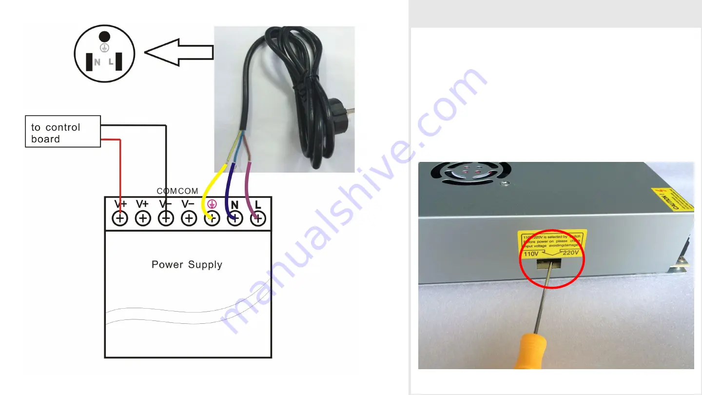
Step 15  AC Power Connector Wiring Diagram

Connect Power cable as the picture (Left)

Note: 

There are different voltages in different 

country.  Please select the appropriate voltage by 
switch before power on. As the picture below.

Summary of Contents for X5

Page 1: ......

Page 2: ...Assemble Base Frame Parts 2020 Aluminium profile 355mm 2pcs 2020 Aluminium profile 380mm 2pcs 2020 Aluminium profile 500mm 4pcs Acrylic corner cushion 4pcs M4 10mm screw 8pcs M4 T Nut 8pcs M5 25mm screws 4pcs ...

Page 3: ...Step 2 Assemble Top Frame Parts 2020 Aluminium profile 355mm 2pcs 2020 Aluminium profile 380mm 2pcs Corner bracket 8pcs M4 8mm screws 16pcs M4 T Nut 16pcs M5 25mm screws 4pcs ...

Page 4: ...pcs M2 10mm 2pcs M3 16mm 1pcs M3 nut 1pcs 3 Z axis motor 1pcs Z motor holder acrylic 1pcs M3 45mm screws 4pcs M4 10mm screws 2pcs M4 T Nut 2pcs coupling 1pcs Lead screw 385mm 1pcs 4 Flange bearing 2pcs Copper nut 1pcs M3 45mm screws 1pcs Spring 3pcs Flange bearing holder 1pcs M3 10mm screws 8pcs 5 KFL08 bearing 1pcs Sliding rod holder 2pcs M4 10mm screws 6pcs M4 nuts 6pcs Sliding rod 460mm 2pcs 2 ...

Page 5: ...Step 4 Assemble KP08 Bearings Parts KP08 Bearing 4pcs M4 8mm screws 8pcs M4 T Nut 8pcs ...

Page 6: ...Step 5 Assemble SK8 support shaft Parts SK8 support shaft 4pcs M4 8mm screws 8pcs M4 T Nut 8pcs ...

Page 7: ...Step 6 Assemble sliding rods Parts Sliding rod 420mm 2pcs Pulley with grub screw in it 5pcs Closed belt 1pcs ...

Page 8: ...tep 7 Assemble X pulley motor mount Parts Sliding rod 395mm 2pcs LM8UU linear bearing 8pcs X Pulley mount 1pcs X motor mount 1pcs Y endstop 1pcs Y endstop mount 1pcs M2 10mm 2pcs M3 16mm 1pcs M3 nut 1pcs ...

Page 9: ...arts Belt pulley 1pcs M5 32mm screw 1pcs M6 washer 3pcs M5 washer 2pcs M5 nut 1pcs X endstop 1pcs X endstop holder acrylic 1pcs M2 10mm screw 2pcs M2 10mm nut 2pcs M3 40mm nut 2pcs Sliding rod 360mm 2pcs Extruder assembly 1pcs ...

Page 10: ... ties 2pcs Tighten one end of the timing belt to the belt hole which is on the extruder using a zip ties Run the other end of timing belt to the X Motor Pulley and Belt pulley Then tighten it to another belt hole using a zip ties as shown in the picture ...

Page 11: ...pcs Belt clip 4pcs M3 10mm screws 8pcs Tighten one end of the timing belt using belt clip and M3 10mm screws the other end through pulley from left and right side the tighten it on the pulley mount as picture The same install method for X motor mount ...

Page 12: ...Step 11 Assemble Base Frame Parts Bed holder aluminium 2pcs Heat bed 1pcs M3 35mm 4pcs Springs 4pcs Wing nut 4pcs M4 10mm 4pcs ...

Page 13: ...Parts Power supply 1pcs Power supply holder acrylic 1pcs M3 10mm screws 3pcs M4 12mm screws 3pcs M4 T Nut 3pcs Mainboard 1pcs Mainboard holder acrylic 1pcs M3 20mm screws 4pcs Plastic Pillar 4pcs M3 nut 4pcs M4 12mm screws 3pcs M4 T Nut 3pcs ...

Page 14: ...Step 13 Assemble LCD display Parts LCD display 1pcs LCD display holder 1pcs M3 20mm 4pcs M3 nuts 4pcs Plastic pillar 4pcs Control knob 1pcs M4 12mm screws 3pcs M4 T Nut 3pcs ...

Page 15: ...Step 14 Control Board Wiring Diagram X No Connection The method of connecting wire is as picture NOTE The wires connected to POWER SUPPLY and HETBED must be AWG14 or thicker one ...

Page 16: ... Power Connector Wiring Diagram Connect Power cable as the picture Left Note There are different voltages in different country Please select the appropriate voltage by switch before power on As the picture below ...

Reviews: