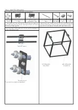
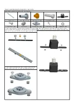
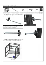
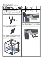
background image

Aluminum4

switch base

1pcs

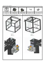
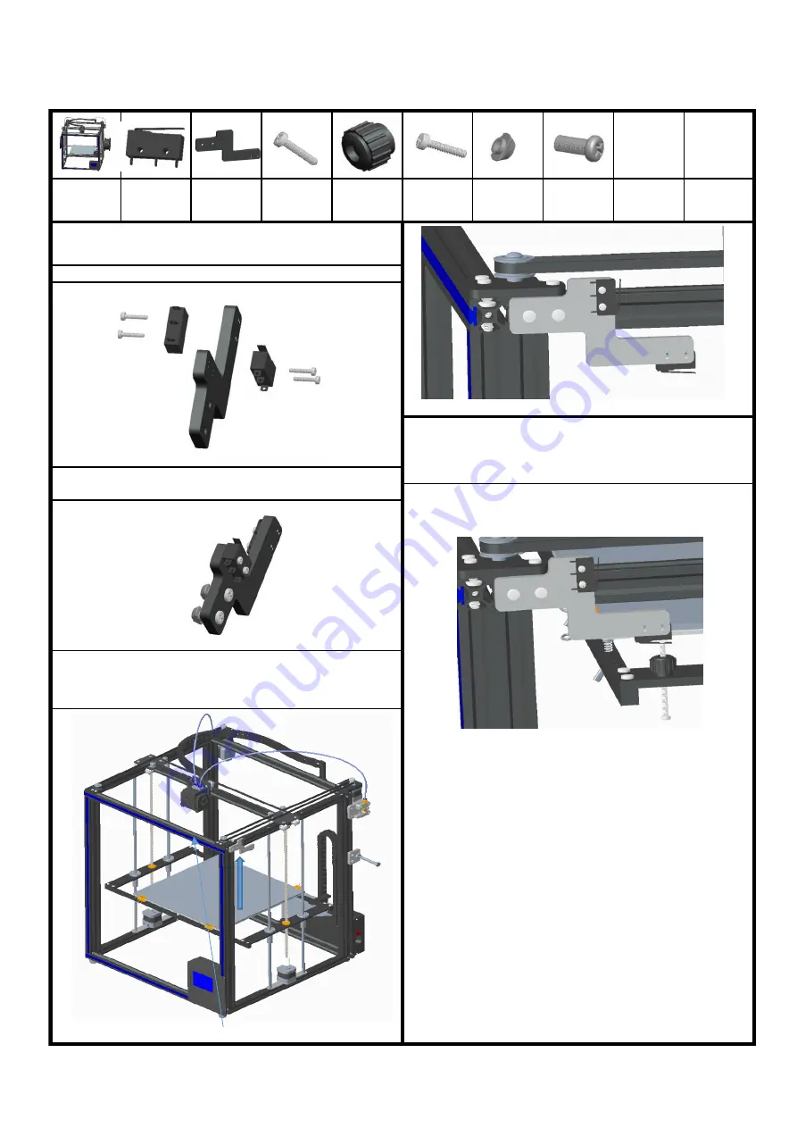
2. Put the switch assembly into 2 screws PM4*9 according to the
position shown, and screw the on-board nut M4

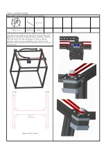
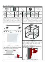
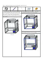
4. Take 1 screw PM3* 45,1 plastic nut M3, screw in according to
the position shown, and pass through the screw tooth hole of
horizontal plate M3.After adjusting the hot bed and screw PM3*45
to the appropriate height, tighten the plastic nut.

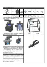
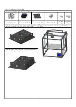
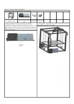
Assembly material specification and quantity:

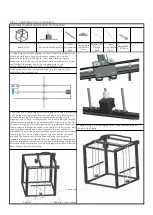
Step 14: limit switch assembly

boat nutsM4

2pcs

screw

PM4*9  2pcs

plastic

nutsM3

1pcs


Switch(incl

wiring)  2pcs

screwPM3*4

5  1pcs

mainframe

1pcs

Note: the screw's torque is small, not too hard.

screwPB2*1

0  4pcs

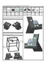
1. Take 1 piece of switch seat and 2 pieces of switch, and insert 2
screws PB2*10 into it respectively according to the position shown
in the picture, and lock the screws.

3. Fix the switch assembly in the aluminum profile groove with
boat nut, as shown in the figure. The edge of the switch seat is
aligned with the end face of aluminum profile 4, and lock the 2
screws PM4*9, as shown in the figure.

Summary of Contents for X5S 2E

Page 1: ...m on the aluminum profile 1 about 20mm away from the end Assembly technique of M4 boat nuts first align the M4 nut with the aluminum profile groove and put it into the aluminum profile groove Unscrew with the screwdriver and release the M4 boat nut to cross the aluminum profile inner groove and then screw it forward Step 1 assemble the underframe Assembly material specification and quantity Alumin...

Page 2: ...hown in the figure Screw on 4 PM5 25 screws do not lock tightly to facilitate subsequent adjustment The eccentric nut Sink hole location screwPM4 8 4件 The eccentric nut clearance adjustment left sliding plate components 1pcs Assembly material specification and quantity underframe 1pcs screwsPM5 25 4pcs right sliding plate components 1pcs Aluminum2 20 20 460 2pcs Note the pulley is on the side with...

Page 3: ...me 1pcs Aluminum4 20 20 484 1pcs nuts M3 4pcs 3 The aluminum 4 components in the left side of the chassis components of the boat nut screw screws on the sliding plate PM4 8 as shown move aluminum4 move and flexible locking PM4 8 screws move aluminum 4 again move and flexible locking in aluminum 1 2 PM5 25 screw move aluminum 4 again confirm the move and flexible Otherwise please adjust it repeated...

Page 4: ...motor and 1 piece of Y motor board align them at the position as shown in the figure use 4 screws of PM3 10 screw into the motor and fasten them use 2 screws of PM4 12 through the acrylic board and screw on 2 ship type nuts M4 Similarly assemble X motor component 1 as shown 1 Place the X Y motor component left right via wheel component and fix it on the aluminum profile with boat nut M4 according ...

Page 5: ...e plate against the motor bottom plate and fasten it with the tie belt at the lower end of the sheet metal groove of the print head assembly Loosen the motor baseplate screw pull the motor assembly outward tighten the belt do not force too much and lock the screw Step 5 assemble the belt Assembly material specification and quantity belt 2pcs Tie 4pcs ...

Page 6: ...pcs Step 6 assemble linear bearing and z axis motor Assembly material specification and quantity gasketM4 4pcs screwPM4 9 4pcs 3 Take 1 piece of motor component of Z axis insert 2 screws PM4 12 as shown and screw on 2 boat nuts M4 Assembly 2 sets 2 Take 1 piece of bearing block insert 2 screws PM4 9 into the position shown and screw on 2 boat nuts M4 Assembly 2 sets Z axis motor component 2pcs lin...

Page 7: ...ate assembly to make sure it is flexible Otherwise please loosen the screw and adjust it again Finally lock the 4 meter screws on the coupling and the boat nut screws on the motor board Turn the screw again to make sure that the board slides up and down smoothly 3 Repeat step 2 to assemble another z axis slide carriage as shown in the figure Note when the screw rod is assembled the tail is about 3...

Page 8: ...on the right side of the diagram 2 Use 2 PM4 12 screws and boat nut M4 to lock the feeding motor components to the left in the left position shown Step 8 feed motor installation Assembly material specification and quantity boat nutsM4 4pcs frame 1pcs left feed motor component 1pcs screwPM4 12 4pcs right feed motor component 1pcs ...

Page 9: ...ake sure the movement is flexible Otherwise loosen the screw PM4 12 to adjust screwPM4 1 2 8pcs Note you can twist the tow link head of the second end of the chain tighten the screw and install it screwPM4 12 2 Take 1 piece of drag chain bracket and fasten it to the beam with PM3 10 screws according to the position shown 4 Take 2 KB3 8 screws as shown in the figure and tighten the chain support an...

Page 10: ... nut on the aluminum profile The fan cover 1pcs the position shown and lock them with 4 PM3 4 screws and main board assembly as shown as shown Assembly material specification and quantity Main components 1pcs 1 Take the main board assembly and fan cover plate place them in mainframe 1pcs Step 10 motherboard assembly boat nutsM4 3pcs ...

Page 11: ...and slide the gear into 220V as shown in the figure Select 110V and slide the shift to 110V Assemble the boat nut M4 and screw PM4 9 in the position shown Step 11 power supply installation Assembly material specification and quantity 2 Fix the aluminum profile groove with the boat nut and lock the 3 screws PM4 9 as shown in the figure mainframe 1pcs power 30A component 1pcs screwPM4 9 3pcs boat nu...

Page 12: ...and screw on the on board nut M4 as shown in the figure Repeat 1 2 steps to assemble the other 3 Fix the material rack assembly into the aluminum profile groove with boat nut and lock the 2 screws PM4 12 as shown in the figure hang the material plate on the screw rod screwPM4 12 4pcs Step 12 assemble the filament rack Assembly material specification and quantity hex screwM8 100 2pcs mainframe 1pcs...

Page 13: ...nto the aluminum profile groove as shown in the figure 1 Pull the feeding tube into the air nozzle hole of the feeding component press down the plastic outer ring of the air nozzle insert the feeding tube loosen the plastic ring and jam the feeding tube as shown in the figure Make sure the material tube is jammed Then put the other end of the feeding tube into the air nozzle of the printing head a...

Page 14: ...d quantity Step 14 limit switch assembly boat nutsM4 2pcs screw PM4 9 2pcs plastic nutsM3 1pcs Switch incl wiring 2pcs screwPM3 4 5 1pcs mainframe 1pcs Note the screw s torque is small not too hard screwPB2 1 0 4pcs 1 Take 1 piece of switch seat and 2 pieces of switch and insert 2 screws PB2 10 into it respectively according to the position shown in the picture and lock the screws 3 Fix the switch...

Page 15: ...display screen 5 Insert the 10P wire out of the extruder head and the red and black terminal FAN1 logo of the wire into the FAN1 terminal seat of the main board The blue and black terminal FAN2 logo is inserted on the FAN2 terminal seat of the main board The green and black terminal is inserted on the X STOP terminal seat of the motherboard 2 white terminals are inserted on the ETEMP terminal seat...

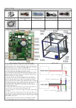
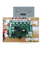
Page 16: ...Wiring diagram of main board ...

Page 17: ...stem menu and enter it into the system submenu as shown in the figure click back menu and return to the superior menu 2 1 click the state and display as shown in the figure display the machine position state parameters Click back menu to return to the superior menu 2 2 click the machine information and display the following figure display the machine brand ID version and other information Click ba...

Page 18: ...enu 2 4 click factory Settings to ask whether the factory Settings are restored Click to return to restart and restore the factory Settings 2 5 click the screen correction enter the screen correction and click the cross position for correction Adjust the screen when clicking the menu deviation save the return ...

Page 19: ...e the icon of E1 to display E2 Click on the icon of E2 again to display E1 as shown in figure E1E2 When displaying E1 click icon E to start extruder 1 when displaying E2 click icon E to start extruder 2 3 2 click the icon of preheating as shown in the figure set the heating temperature of the machine extrusion head and the hot bed heat the icon hot bed and heat the icon extrusion head and click th...

Page 20: ...ed As shown in the figure pass the consumables through the feeder hole reach the consumables and insert the consumables into the bottom of the extrusion head Click the icon to send the material to the nozzle Click the icon to stop feeding Also insert another filaments and material pipes 3 3 2Enter the manual menu and switch to E1 Set the moving length to 10mm Click return 40mm click E1 to switch t...

Page 21: ...on head about 2 3mm away from the moving platform and lock the switch adjusting screw nut Click screen X the extruder head move to the set position then loosen the adjusting nut of the hot bed and fine tune the platform to make the distance between the platform and the nozzle to an A4 paper thickness gap size Slide the nozzle to a sheet of A4 paper between the nozzle and the platform with resistan...

Page 22: ...e folder open the folder and display the folder contents 4 1 click on the file and select the file which is a sliced file to enter the file screen Click the icon to delete the file Click on the icon go into print mode Top left frame preview model The right picture frame shows the status parameters the green hourglass shows the printing time and the blue hourglass shows the time needed after printi...

Page 23: ...no machine state reset Click cancel to continue printing This function continues for breakpoint Boot prompt did not print last time select to continue printing last time 4 1 3 click the icon to enter the machine parameter setting change The initial parameters are set by slicing software The parameters can be changed in printing as shown in the figure corresponding to the icon parameters Click the ...

Page 24: ...ng the machine will automatically save the current status parameters When the machine is restarted the screen will show that the last time it was hit was interrupted The option is to print from the breakpoint Select no or cancel and the parameters are cleared ...

Page 25: ...sy to cause the pipe blocking material The pipe should be removed and cleaned 3 Poor quality filaments lead to poor feeding filaments replace high quality filaments after removing the 4 Problems such as not reading the card and online failure 3 FAQ 1 Nozzle plugging material will the print head heated to above 180 and then use the 0 4 mm default needle dredge nozzle until manual feeding normal out...

Reviews: