
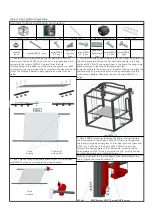


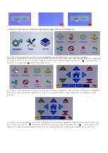


9. Plug in the power cord, connect the power, and debug the machine.
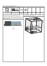
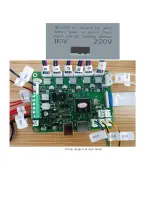
6. Connect the Power supply connection to the Power supply terminal of
the main board, red positive pole and black negative pole.
7. Select the voltage of 110V/220V according to the power supply voltage
in the region.
10. After debugging, tidy the wires and tie them with wrapping tape.
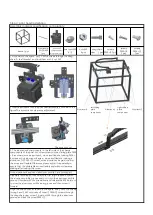
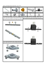
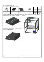
USB cable 1pcs
mainframe 1pcs
The motor wire 4P*6
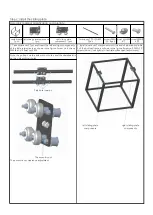
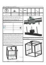
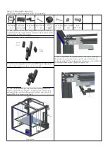
Step 15: wiring
Assembly material specification and quantity:
Switch wire assembly
2pcs
Wrapping tape 1roll
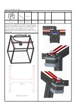
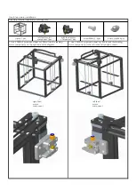
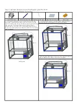
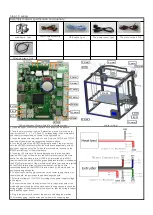
3. Insert the switch wire terminals of Y and Z into the Y STOP and Z STOP
terminals of the main board respectively.As shown above.
4. Lock the 4P wire of the HOTBED outgoing line and 2 red dip tin wires
onto the HOTBED terminal block of the main board respectively, with no
positive or negative poles.The 2 white line terminals are inserted on the
BTEMP terminal seat of the motherboard.
The power cord 1pcs
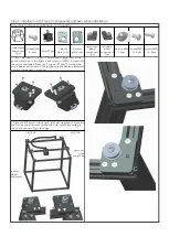
1. Open the upper cover of the control box to reveal the mainboard.
Wiring diagram of main board and display screen
5. Insert the 10P wire out of the extruder head and the red and black
terminal FAN1 logo of the wire into the FAN1 terminal seat of the main
board;The blue and black terminal FAN2 logo is inserted on the FAN2
terminal seat of the main board;The green and black terminal is inserted on
the X STOP terminal seat of the motherboard;2 white terminals are inserted
on the ETEMP terminal seat of the motherboard;2 red dip tin wire,
respectively locked on the HOTEND terminal block of the main board, no
positive and negative poles.
8. Connect the red line of the upper cover fan to the positive pole of the
mainboard power supply and the black line to the negative pole, check the
wiring diagram of the physical object, and confirm that the wiring is correct,
and install the upper cover.
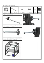
2. Take the motor connection wire (5 pieces) and insert it into the motor
terminal seat of X, Y, z-1, z-2, E and E2 corresponding to the main board
and the motor respectively, as shown in the figure above.
printer wiring
Z1-motor1
Z2-motor
X-motor
Y-motor
E2-motor
Z STOP
Y STOP
X STOP
Fan 2
Fan 1
Heat
E-motor
-DC12V+
BTEMP
ETEMP
FAN2
FAN1
E-motor
Z2-motor
Z1-motor
Y-motor
X-motor
HOTBED
HOTEND
X STOP
Y STOP
Z STOP
E2-motor
Summary of Contents for X5S 2E
Page 16: ...Wiring diagram of main board ...


