
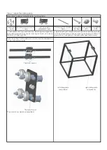
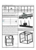


Hole
location
Position of
wire outlet
Hole
location
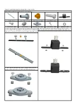
M3 Nut
PM4*8 screw PM3*10 screw PM3*6 screw
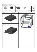
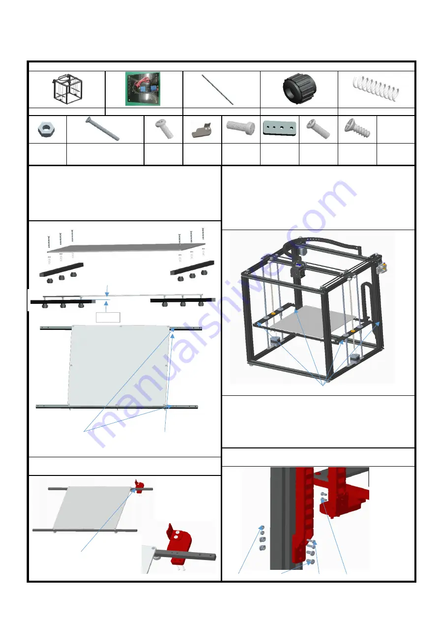
1. Take the hot bed, pass through the hot bed with 6 KM3*30
screws, and lock it with M3 nut, as shown in the figure;Insert the
spring into the screw of KM3*30, extend from the hole
corresponding to the beam, and screw into the plastic nut of M3
to adjust the spacing between the hot bed and the beam by about
10mm.The relation between beam position and wire is shown
below.
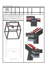
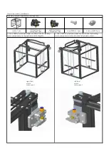
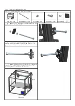
3. Turn the two screw rods to make the left and right side plates on
the same plane and fasten the hot bed components to the side
plates with 8 PM4*12 screws,as shown in the figure.The drag chain
bracket is close to the side of the feeding motor
component.Rotate the screw rod in the same direction to make the
platform move up and down synchronously,and make sure the
movement is flexible. Otherwise, loosen the screw PM4*12 to
adjust.
screwPM4*1
2 8pcs
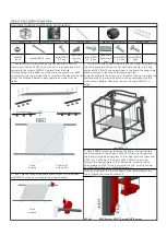
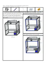
Note: you can twist the tow link head of the second end of the
chain, tighten the screw and install it.
screwPM4*12
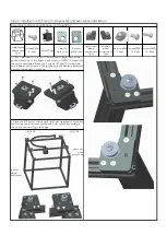
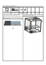
2. Take 1 piece of drag chain bracket and fasten it to the beam
with PM3*10 screws according to the position shown.
4. Take 2 KB3*8 screws, as shown in the figure, and tighten the
chain support and chain;Take 2 PM3*10 screws, go through the
chain and drag the bottom plate of the chain, and lock them with
2 M3 nuts. As shown in the figure, take 2 PM4*8 screws, go
through the bottom plate of the chain chain, screw on the on-
board shape nut M4, lift the hot bed to the top, finish the chain,
and lock the aluminum profile with boat nut.
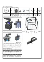
drag chain
baseboard
1pcs
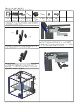
hotbed 330*330*3 1pcs
Step 9: print platform assembly
Assembly material specification and quantity:
drag chain
support
1pcs
screwKM3*30 6pcs
screwsPM3*
10 2pcs
screwKM3*1
0 2pcs
nutsM3
8pcs
plastic nutsM3 6pcs
beam 2pcs
frame 1pcs
screwKB3*8
2pcs
spring 6pcs
10mm
Summary of Contents for X5S 2E
Page 16: ...Wiring diagram of main board ...


