background image

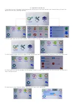
2. operation instructions

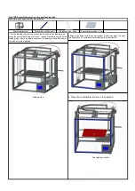
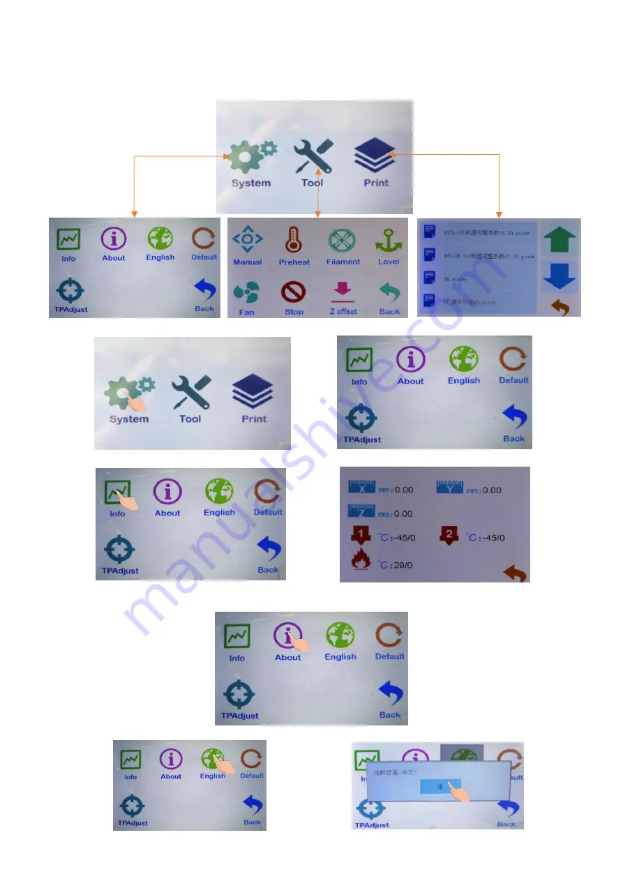
1. Enter the main screen of the startup, display the system and tools, print three main menus, and click on the three sub-menus, as shown in the
figure.Basic functionality for displaying submenus.

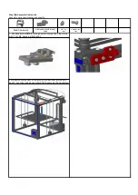
2. Click the system menu and enter it into the system submenu, as shown in the figure: click back menu and return to the superior menu.

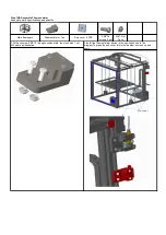
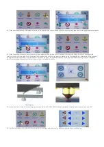
2.2 click the machine information and display the following figure: display the machine brand, ID, version and other information.Click back menu to
return to the superior menu.

2.3 click the menu to enter Chinese and English.Click back menu to return to the superior menu.

2.1 click the state and display as shown in the figure: display the machine position state parameters.Click back menu to return to the superior menu.

Summary of Contents for X5SA

Page 1: ...X5SA Installation instructions SHENZHEN TRONXY TECHNOLOG CO LTD ...

Page 2: ...e 3 20 40 530mm 4pcs 1 Lock the aluminium profile 1 2pcs Aluminium profile 2 2pcs aluminium 3 4pcs together by 8pcs screw PM5 25 same as the illustration Note Before locking the screws make sure the aluminum profile are aligned and vertical Step 1 Assemble base frame Assemble parts specifications and quantity T nut M4 4pcs 3 Lock the aluminium profile 1 2pcs with 4pcs screw PM5 25 Note Do not tigh...

Page 3: ...s Assemble parts specifications and quantity Alu profile 2 20 20 460mm 2pcs Screws PM5 25mm 4pcs PM4 8mm screws 4pcs M4 T nut 4pcs 1 Respectively insert 2pcs PM4 8mm screws to Left and Right slider plate lock with M4 T nut as same as the illustration 3 Put the aluminum 2 components into the end of the aluminum frame 3 of the bottom frame then secured by 4pcs screw PM5 25 as same as the illustratio...

Page 4: ...as the illustration The eccentric nut Adjust pulley clearance by rotating eccentric nut 4 Put the aluminum 4 component into the T nut of the left and right slide plate component screw the screw PM4 8 of the slide plate same as the illustration Move the aluminum profile 4 front and back make sure it can move freely then lock the screw PM4 8 remove the aluminum 4 ensure it can move freely lock the s...

Page 5: ...Y motor and X Y motor base plate using 4pcs PM3 10mm screws Respectively insert 2pcs PM4 12mm screws to the plates lock with M4 T nuts see the illustration 3 Fix the X motor component Y motor component left pulley component right pulley component and aluminum by PM4 12mm screws and M4 T nut as same as the illustrations Screws PM3 10 8pcs Y Motor base plate 1pcs Framework Pulley component Right 1pc...

Page 6: ...n the belt do not force too much and lock the screw 2 Pass the belt through the gear as shown press the pulley plate against the motor bottom plate fasten the lower end of the sheet metal groove of the print head assembly with the tie belt as shown in the figure After adjusting the spacing between the motor gear and the belt lock the 2 meter screws on the gear Loosen the motor baseplate screw pull...

Page 7: ...ble 1pc Z motor component 2pcs screw PM4 8mm 2pcs Elastic gasket and 2pcs T nut M4 together total need to assemble 2 set 2 Assemble 1pc bearing seat 2pcs screw PM4 8mm 2pcs T nut M4 together same as the illustration total need assemble 2set M4 T Nut 8pcs Bearing seat 2pcs 1 Assemble 1pc Z fixed plate 2pcs bearing seat 1pc screw nut 12pcs screw PM3 8 together as the illustration total need to assem...

Page 8: ... assemble other Z aixs carriage as the illustration Z carriage 2pcs 2 Adjust the T nut on the Z motor component Place the Z motors to the aluminum profile 2 the 2 small M3 holes stand outsite as the illustration Align sliding rod Φ 8 528 with the hole of the aluminum profile let screw PM4 20 through the holes of the aluminum profile 2 then connect with the M4 hole of the sliding rod Φ 8 528 same a...

Page 9: ... with 2pcs screw PM4 12 and T nut M4 same as the illustration 1 Put 2pcs screw PM4 12mm through the board holder then lock them with the T nut M4 screw on the boat nut M4 Assemble parts specifications and quantity Main framework Feeding motor component 1pcs Screws PM4 12 2pcs M4 T Nut 2pcs ...

Page 10: ... and keep 10 mm between the heat bed and the metal bar 3 Rotate 2pcs lead screws T8 453 keep 2 Z carriage at the same plane secure the heat bed component and metal bar with 8pcs screw PM4 12 The towline bracket is close to the side of the feed motor component rotate the screw in the same direction let the platform move up and down make sure it can move freely if not freely please lossen the screw ...

Page 11: ...p position 2 The main board components are loaded into the lower right corner of the machine and are fixed in aluminum grooves with T nuts 4 Load the power assembly into the lower right corner of the machine and use the T nut to fix it in the aluminum slot Screw PM4 6 3pcs Screw PM4 8 3pcs Step 10 Assemble electronic board and power supply Assemble parts specifications and quantity Main frame 1pc ...

Page 12: ...crewsPM4 6 2 boat nut M4 assemble as shown 2 Fix the material rack assembly into the aluminum profile groove with boat nut and lock the 2 screws PM4 6 as shown in the figure hang the material plate on the screw rod Main framework Step 11 Assemble feeding holder Assemble parts specifications and quantity ...

Page 13: ...plastic ring of Air cock loosen the plastic ring stuck the feeding tube same as illustration move the feeding tube up and down to make sure it is clenched 2 Align the end seal with the end aluminum profile then press the seal into the groove of the aluminum profile same as illustration 3 Place the print platform sticker on the heatbed Main framework Aluminium profile seal Feeding tube 1pcs Print p...

Page 14: ...8 through switch component then lock with T nut M4 same as illustration Step 13 Assemble limit switch Assemble parts specifications and quantity 2 Fix switch component in the groove of aluminum profile with 2pcs T nut then lock 2pcs screw PM4 8 same as the illustration Main framework ...

Page 15: ...he diagram To press the end cover into two side aluminum end up and down End cover 1 Put 2pcs screw PM4 12 through cushion plate then lock with T nut M4 same as illustration Main framework Filament alarm 1pc End cover 8PCS Step 14 Assemble Filament alarm Assemble parts specifications and quantity ...

Page 16: ... ZSTOP HOTBED Power X Motor Y Motor Z1 Motor Z2 Motor E Motor YSTOP FSTOP Step 15 Connecting wire Printing head Z1 motor Z2 motor Y Motor X Motor E motor Heat bed Printing head The host box Power YSTOP FSTOP ...

Page 17: ...X5SA Physical wiring diagram F STOP ...

Page 18: ...hown in the figure click back menu and return to the superior menu 2 2 click the machine information and display the following figure display the machine brand ID version and other information Click back menu to return to the superior menu 2 3 click the menu to enter Chinese and English Click back menu to return to the superior menu 2 1 click the state and display as shown in the figure display th...

Page 19: ...he screen when the menu is off save it back 3 Click the tools menu to enter the machine parameter setting and adjustment 3 1 click the manual menu and enter the manual adjustment mode Adjust the motor rotation e extruder feeding discharging XYZ shaft motor moving ICONS 0 01mm 0 1mm 1mm 10mm click on the dark display such as icon 10mm each click on the motor stroke moving 10mm Click the icon and th...

Page 20: ...Remove the consumables to warm up before pulling them out Set the heating temperature the temperature reached click the icon to return the material When installing the filaments make the filaments go straight out into the hole of the filament run out detector and press down the feeder s pressing block as shown in the figure Pass the filaments through the feeder to the filaments pipe and then click...

Page 21: ...er A4 paper between the nozzle and the platform moving a sense of resistance but will not cut paper Please adjust the four points circled in A4 paper thickness 3 5 click the fan icon to enter the fan setting and turn the fan value 0 OFF 100 ON Click the number box directly to switch between 0 and 100 3 6 Click the emergency icon the machine stops in the current state and the motor unlocks Stop hea...

Page 22: ...o scroll up and down Click the folder open the folder and display the folder contents 4 2 click on the file and select the file which is a sliced file to enter the file screen Click the icon to delete the file Click the icon to enter print mode Top left frame preview model The right picture frame shows the status parameters the green hourglass shows the printing time and the blue hourglass shows t...

Page 23: ...ange The initial parameters are set by slicing software The parameters can be changed in printing as shown in the figure corresponding to the icon parameters Click the parameters on the right side of the icon enter the parameter setting screen set the parameters click the icon to save and exit and click the icon to exit without saving 5 Filament run out detector when the machine is working the con...

Page 24: ...e is loose the heating block is loose and the throat tube is loose or worn out due to use replace accessories 6 Print the wrong layer loose the belt and tighten the belt properly 3 FAQ 1 Nozzle plugging material will the print head heated to above 180 and then use the 0 4 mm default needle dredge nozzle until manual feeding normal out of filaments 2 Pipe plugging material the printing head is a st...

Reviews: