background image

3

Operating Manual – Thermal Imaging Camera AC080V

EN

Device description

The thermal camera AC080V creates a visible image depicting
infrared radiation which is otherwise invisible to the human eye.
The thermal image and temperature are displayed on the screen
in real time. To improve the view, you can select various colour
palettes for depicting the thermal image. 
You are also able to automatically find and display the warmest
and coolest measuring spot in the measured image.
For a measured result which is as precise as possible the ambient
temperature, relative humidity, distance and degree of emission
can be entered. 
A list of degrees of emission for various surfaces is provided in
chapter Degree of emission.
For a precise evaluation, the thermal image on the screen can be
recorded and saved on the device.
The device control is based on the Android operating system for
tablets.
The saved images can either be viewed directly on the screen or
transferred to a PC with the supplied USB cable.
To edit the images, you can download the IR-Report 2.X STD
software from the download (or service) section of
www.trotec.com.

Note:

Described in this operating manual is only the operation of the IR
app for the AC080V. Further functions of the tablet or the Android
operating system are not a part of this manual. 

Additionally, to create short reports relating to the images, you
can use the app IR-Wizard available free of charge. This software
is a complimentary bonus that does not belong to the standard
scope of delivery and is offered for use without support or
warranty. The program interface (only available in selected
languages) is generally easily comprehensible 
and can be used intuitively. Further information regarding the use
is provided in the application.

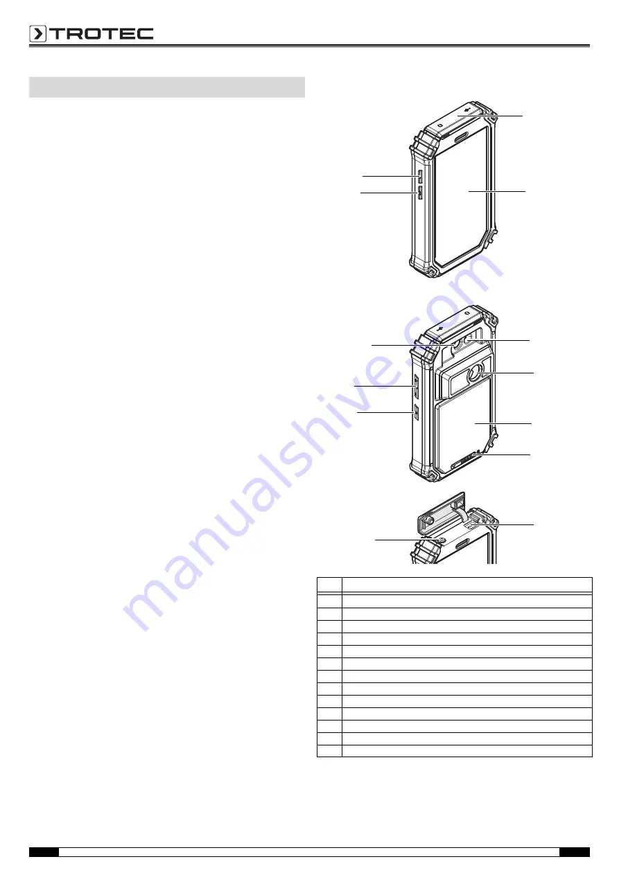
Device depiction

Information about the device

No.

Operating element

1

Protective cover for micro USB and headphone connection

2

Touch screen

3

LED illumination

4

Infrared camera

5

Battery compartment with cover

6

Locking mechanism for the battery compartment

7

USB connection

8

3.5 mm headphone connection

9

Power button 

10

Volume control button

11

Camera (visual)

12

Photo button (IR picture)

13

Shutter button

4

2

3

1

5

6

9

10

11

7

8

12

13

Summary of Contents for AC080V

Page 1: ...AC080V OPERATING MANUAL THERMAL IMAGING CAMERA EN TRT BA AC080V TC 001 EN...

Page 2: ...nges to the shape and colour are reserved The scope of delivery may vary from product images This document was created with all due care Trotec accepts no liability whatsoever for possible mistakes or...

Page 3: ...e device on persons or animals Trotec accepts no liability for damages resulting from improper use In such a case entitlements to a warranty are forfeited Any unauthorised modifications alterations or...

Page 4: ...o edit the images you can download the IR Report 2 X STD software from the download or service section of www trotec com Note Described in this operating manual is only the operation of the IR app for...

Page 5: ...scale 16 Camera control panel 17 Mode menu bar 18 Functions menu bar example here Analysis 19 Parameter button 20 Charging status indicator 21 Menu button 22 Home button 23 Back button 24 Still image...

Page 6: ...ptions IR image IR video real image Measurement and analysis Measuring spots Five dynamic temperature measuring spots individually configurable MIN MAX ALARM Measuring functions Isotherm sector analys...

Page 7: ...e battery when storing the device for a longer period of time Preferably use the supplied transport case to store the device Inserting the battery Caution Make certain that the surface of the device i...

Page 8: ...to leave the system settings Setting the time and date Time and date of the app are controlled via the system settings of the Android operating system 1 Call up the system settings The system setting...

Page 9: ...is mode 3 Point the camera at the object which you want to have a thermal image of 4 Calibrate the IR camera see Calibrating the IR camera 5 Either press the Photo button 12 or the camera icon on the...

Page 10: ...omatic calibration 4 Press Confirm to confirm and save the selection If you do not want to save the change press Cancel 5 Press the Back button 23 to leave the menu Note If the automatic adjustment fu...

Page 11: ...rameter 3 Press Confirm to confirm and save the selection If you do not want to save the change press Cancel 4 Press the Back button 23 to leave the menu or briefly touch a free area on the touch scre...

Page 12: ...eave the submenu or briefly touch a free area on the touch screen The settings will be saved Photo settings submenu In this submenu you can adjust the thermal image display 1 Press the button with the...

Page 13: ...button 24 to freeze an image for analysis Point analysis 1 Press the button for points 33 Crosshairs appear on the display beside which the current temperature of the point is indicated 2 Touch the sp...

Page 14: ...separate area analysis within the thermogram 1 Press the button for rectangles 35 or circles 36 2 Touch the starting point on the display and then stretch the rectangle or circle to be analysed The re...

Page 15: ...o save the change press Cancel Line analysis 1 Press the button for lines 34 The line appears on the display Above and below the line the temperature profile is displayed in form of a chart in the bel...

Page 16: ...on 40 The brightness and contrast menu LEVEL SPAN will be displayed Contrast SPAN set temperature range e g from 5 C to 30 C SPAN 25 C Brightness LEVEL average temperature referring to the set tempera...

Page 17: ...iously specified temperature range isotherm window by means of a selected particularly noticeable colour This can e g be drops below dew point at building surfaces or thermally critical areas in contr...

Page 18: ...17 Operating Manual Thermal Imaging Camera AC080V EN Example ISO Mode Between Example ISO Mode Above Example ISO Mode Below...

Page 19: ...etter it is suited for non contact temperature measurement by use of a pyrometer or thermal imaging camera since falsifying temperature reflections can be neglected Entering a degree of emission as ac...

Page 20: ...xtiles non metal 0 95 Titanium oxidized 0 5 to 0 6 Clay 0 90 to 0 95 Water 0 93 Cement 0 90 to 0 96 Brick rough 0 90 to 0 95 Zinc oxidized 0 1 Material Degree of emission Errors and faults Error Cause...

Page 21: ...evice or install any spare parts For repairs or device testing contact the manufacturer In the European Union electronic equipment must not be treated as domestic waste but must be disposed of profess...

Page 22: ......

Page 23: ......

Page 24: ...Trotec GmbH Co KG Grebbener Str 7 D 52525 Heinsberg 49 2452 962 400 49 2452 962 200 info trotec com www trotec com...

Reviews: