Data logger operating manual
7
EN
7. Measured values display and data recording
7.1. Sensors, channel groups and
measuring channels
The DL200P data logger can detect measured values from up to twelve channel
groups by using two internal sensors and up to four external measured value
sensors.
The internal channel groups (measured values) are: Air temperature in °C, air
temperature in °F, dew point in °C, dew point in °F, relative humidity in % and
absolute humidity in g/m³.
The external channel groups (measured values) are: Temperature in °C, temper-
ature in °F, dew point in °C, dew point in °F and wood or building moisture in
digits.
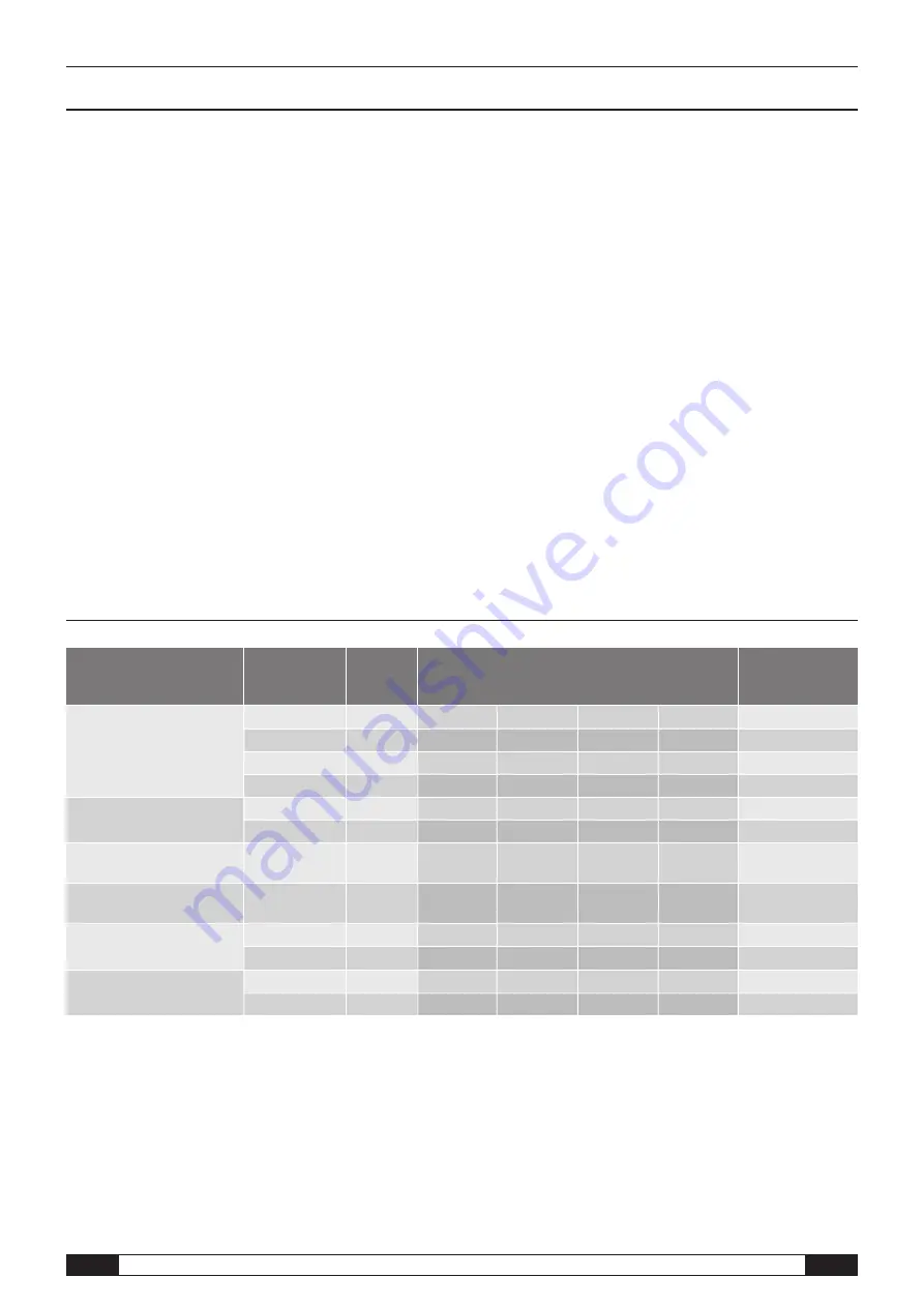
For each channel group, there are four measuring channels for recording:
Current measured value (cur), minimum measured value (min), maximum mea-
sured value (max) and average measured value (mid). In total, there are up to
48 measuring channels available for your DL200P, as shown in table 1.
7.2. Displaying measured values
One of the channel groups specified in table 1 for displaying measured values
can be configured to be displayed on each of the three measured value rows.
Here, the current measured value is always shown on the display.
7.3. Data recording
If either of the operating modes M3 or M4 are selected, then the data logger is
in logging mode (REC) and the measured values of the measuring channels se-
lected for recording are saved in the device.
Up to 20 of the measuring channels specified in table 1 can be simultaneously
recorded in the data memory of the measuring device.
Recording begins immediately from the moment that the operating mode M3 or
M4 is selected and is carried out in ring mode. This means that when the
memory limits are reached, the recording does not stop but continues to record.
The older values are simply overwritten by the newest measured values.
R
Tip: Current, minimum, maximum and average measured values for
a channel group each represent one measuring channel. If these
values should be available for later documentation and evaluation, each of
the measuring channels must already be selected during memory organi-
sation for recording, because it is not possible to calculate these values in
the software.
m
The dew point temperature is its own channel group and thus can-
not be calculated from the measured values of other channel
groups retrospectively during a later evaluation. So, when organising the
memory, select the necessary dew point temperature measuring channels
for recording, as needed.
The specifications for type, duration and scope of data recording in the logging
mode can be individually set in the software. Detailed information is provided in
the software manual.
Table 1: Overview of sensors, channel groups (measured values) and measuring channels of the data logger
Sensor /
measured value sensor
Channel group
(measured value)
Unit
Available measuring channels for data recording
(max. 20 channels available for saving)
and for displaying* (max. 3 channels for display)
Displayable in the
display-measured
value row
internal temperature sensor
Temperature
[°C]
cur
min
max
mid
1, 2, 3
Temperature
[°F]
cur
min
max
mid
1, 2, 3
Dew point
[°C]
cur
min
max
mid
1, 2, 3
Dew point
[°F]
cur
min
max
mid
1, 2, 3
internal humidity sensor
Relative humidity
[%]
cur
min
max
mid
1, 2, 3
Absolute humidity
[g/m³]
cur
min
max
mid
1, 2
external building moisture
electrode 1
BNC1
digits
cur
min
max
mid
1, 2, 3**
external building moisture
electrode 2
BNC2
digits
cur
min
max
mid
1, 2, 3**
external
temperature sensor 1
T1ext
[°C]
cur
min
max
mid
1, 2, 3***
T1ext
[°F]
cur
min
max
mid
1, 2, 3***
external
temperature sensor 2
T2ext
[°C]
cur
min
max
mid
1, 2, 3***
T2ext
[°F]
cur
min
max
mid
1, 2, 3***
* When selecting a channel for display, the current measured value (cur) is always automatically shown.
** If this external building moisture electrode has been configured in SmartGraph software for displaying on the display-measured value row 1, 2 or 3,
but no electrodes are connected to this socket, then “15” is shown in the measured value display.
This information when no electrode is connected is not a device fault and is necessitated by construction.
*** If this external temperature sensor has been configured in SmartGraph software for displaying on the display-measured value row 1, 2 or 3,
but no sensor are connected to this socket, then “E 55” is shown in the measured value display.
This information when no sensor is connected is not a device fault and is necessitated by construction.


