background image

EN

10

Operating manual – rotary hammer PRDS 10-230V

Info

Only use the optional key-type drill chuck in drilling
mode!
The function selector switch with release button (3)

must be set to position 

 and the switch for

the impact mechanism (12) to position 

.

Connecting the power cable

1. Insert the mains plug into a properly secured mains

socket.

Operation

Tips and notes on handling the rotary hammer

Drilling in general:

Take short breaks regularly during drilling. When doing so,
take the drill bit out of the drill hole so that the drill bit can
cool down.

Secure the workpiece in a tensioning device or vice.

Select the speed depending on the material characteristics
and the size of the drill bit:

– High speed for small drilling diameter or soft material
– Low speed for large drilling diameter or hard material

Use a suitable aid to mark the intended location of the drill
hole.

Select a low speed for spudding.

Drilling in metal:

Use suitable metal drill bits (e.g. drill bits made of 

high-

speed steel

 (HSS)).

For larger drilling diameters, use a smaller drill bit for pre-
drilling.

To achieve ideal results, the drill bit should be cooled with
a suitable lubricant.

Metal drill bits may also be used for drilling in plastic.

Drilling in wood:

Use drill bits suitable for wood.

Place a block of wood under the workpiece or drill in from
both sides so that the wood cannot break off when it is
being drilled through.

Use a wood drill bit with centring tip. For deep drill holes,
use an auger bit; for large drilling diameters, use a
Forstner bit.

Impact drilling in masonry / bricks:

Use a drill bit suitable for masonry / bricks.

Chiselling in general:

Use a suitable chisel.

Switching the device on and off

Wear your personal protective equipment when working with
the device.

1. Check whether the tool clamped in and the selected speed

level are suitable for the intended application.

2. Check whether the workpiece is secured and the worktop

prepared correspondingly.

3. If you work with activated impact mechanism, press the

tool against the workpiece.

4. Hold onto the device with both hands.
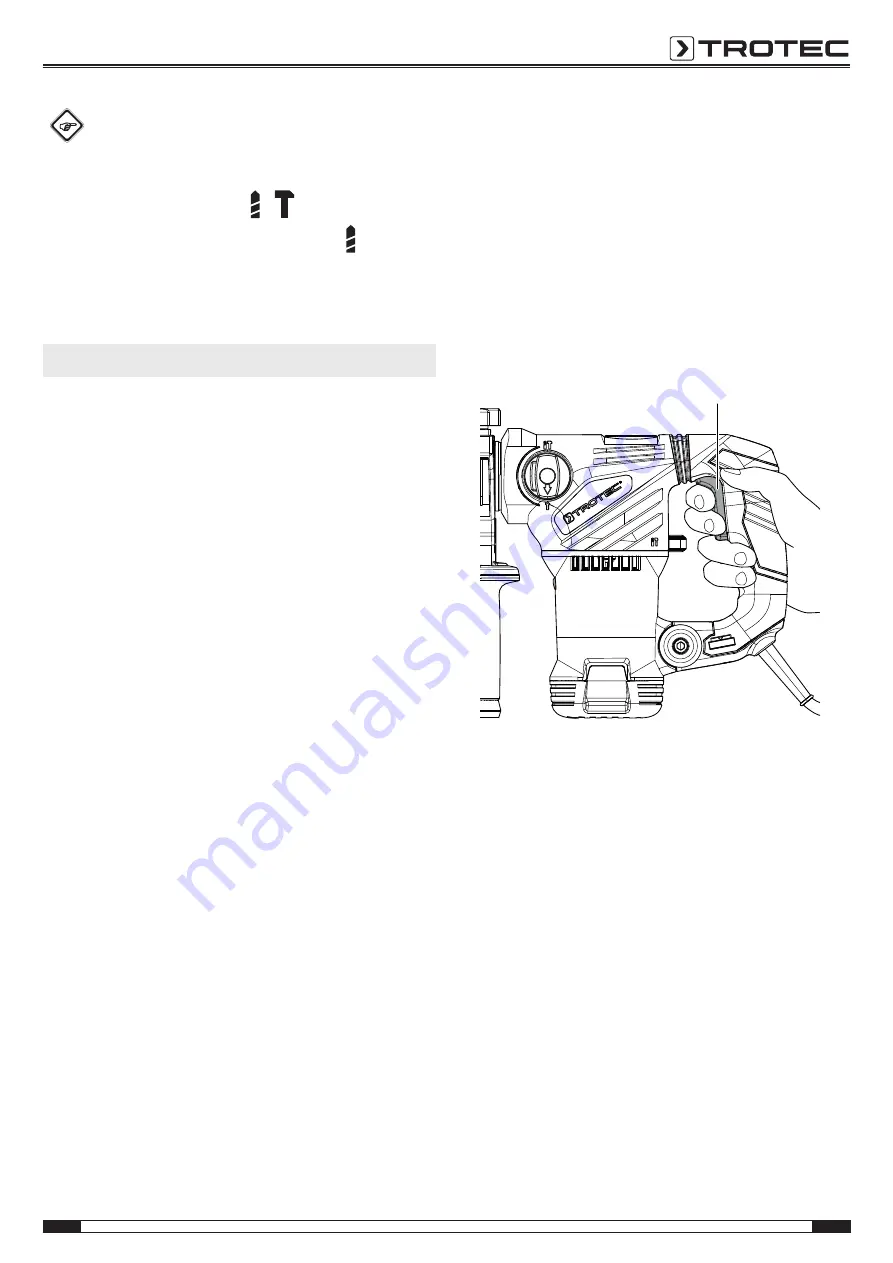
5. Press and hold the power button (4).

ð

The device operates with the previously selected
settings.

4

6. Let go of the on / off switch (4) to stop the device.

Summary of Contents for PRDS 10-230V

Page 1: ...TRT BA PRDS10 230V TC 002 EN PRDS 10 230V EN ORIGINAL INSTRUCTIONS ROTARY HAMMER ...

Page 2: ...uickly and safely Follow the manual Information marked with this symbol indicates that the operating manual must be observed Wear head protection Information marked with this symbol indicates that you should wear protective headgear Wear hearing protection Information marked with this symbol indicates that you should wear hearing protection Wear safety glasses Information marked with this symbol i...

Page 3: ...ctric shock If operating a power tool in a damp location is unavoidable use a residual current device RCD protected supply Use of an RCD reduces the risk of electric shock Hold power tool by insulated gripping surfaces when performing an operation where the cutting accessory may contact hidden wiring or its own cord Cutting accessory contacting a live wire may make exposed metal parts of the power...

Page 4: ...power tool is maintained Device specific safety warnings for rotary hammers Use the additional handle pre assembled at the device Losing control of the power tool may result in personal injury Hold the device by its insulated gripping surfaces when performing an operation where the insertion tool may contact hidden wiring or its own cord Cutting a live wire may make exposed metal parts of the powe...

Page 5: ...longer use the device Do not use the device when the device or your hands are damp or wet Warning of electrical voltage Work on the electrical components must only be carried out by an authorised specialist company Warning of electrical voltage Before any work on the device remove the mains plug from the mains socket Hold onto the mains plug while pulling the power cable out of the mains socket Wa...

Page 6: ...lly adjust the exertion of force to every application and material A function selector switch with safety lock permits the safe switch over between functions The SDS plus system tool holder makes it possible to exchange the insertion tools easily and without the need for further tools Standard drilling accessories can also be used with an optionally installable key type drill chuck The additional ...

Page 7: ...n Excessive noise can lead to hearing loss Information on noise and vibration The vibration level specified in these instructions was determined by means of a measuring method standardized in EN 60745 and can be used for a device comparison The specified vibration emission value may also be used for a preliminary assessment of the exposure Caution Vibration emissions can cause a health hazard if t...

Page 8: ...lowing storage conditions dry and protected from frost and heat ambient temperature below 40 C protected from dust and direct sunlight inside the transport case Start up Unpacking the device Take the transport case out of the packaging Warning of electrical voltage Electric shock from insufficient insulation Check the device for damages and proper functioning before each use If you notice damages ...

Page 9: ...ditional handle releases 13 2 Turn the additional handle 13 into the desired position 3 Retighten the additional handle 13 4 Check the additional handle 13 for tight fit If necessary tighten the additional handle further Speed selection The required speed depends on the material and the operating conditions and can be determined by way of field testing Select a low level for soft materials Select ...

Page 10: ...ore any work on the device remove the mains plug from the mains socket Hold onto the mains plug while pulling the power cable out of the mains socket 1 Push the SDS plus system tool holder 1 to the rear and hold it there 2 Put the key type drill chuck 7 into the SDS plus system tool holder 1 1 7 3 Then release the SDS plus system tool holder 1 4 Check the key type drill chuck 7 for tight fit 5 Ope...

Page 11: ...r drilling diameters use a smaller drill bit for pre drilling To achieve ideal results the drill bit should be cooled with a suitable lubricant Metal drill bits may also be used for drilling in plastic Drilling in wood Use drill bits suitable for wood Place a block of wood under the workpiece or drill in from both sides so that the wood cannot break off when it is being drilled through Use a wood ...

Page 12: ...unction selector switch 3 during operation Otherwise the device might be damaged Note Only operate the switch for the impact mechanism 12 when the device is at a standstill Otherwise the device might be damaged 1 Set the function selector switch 3 to the desired position The function selector switch comes with a safety lock that has to be pushed in first before you can change the switch position 3...

Page 13: ... may cause a risk of injury Accessories Article number 11 piece SDS drill bit and chisel set 6 205 001 101 Errors and faults The device has been checked for proper functioning several times during production If malfunctions occur nonetheless check the device according to the following list Troubleshooting tasks which require the housing to be opened must only be carried out by an authorized specia...

Page 14: ...ized specialist electrical company or to Trotec for repair Maintenance Activities required before starting maintenance Warning of electrical voltage Do not touch the mains plug with wet or damp hands Switch off the device Hold onto the mains plug while pulling the power cable out of the mains socket Allow the device to cool down completely Warning of electrical voltage Maintenance tasks which requ...

Page 15: ... the declaration of conformity The signed declaration of conformity can be found at http hub trotec com id 39780 Declaration of conformity In accordance with the EC Machinery Directive 2006 42 EC Annex II part 1 Section A Herewith we Trotec GmbH Co KG declare that the machinery designated below was developed constructed and produced in compliance with the requirements of the EC Machinery Directive...

Page 16: ......

Page 17: ...Trotec GmbH Co KG Grebbener Str 7 D 52525 Heinsberg 49 2452 962 400 49 2452 962 200 info trotec com www trotec com ...

Reviews: