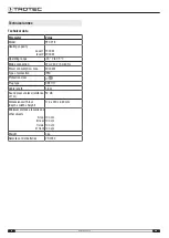
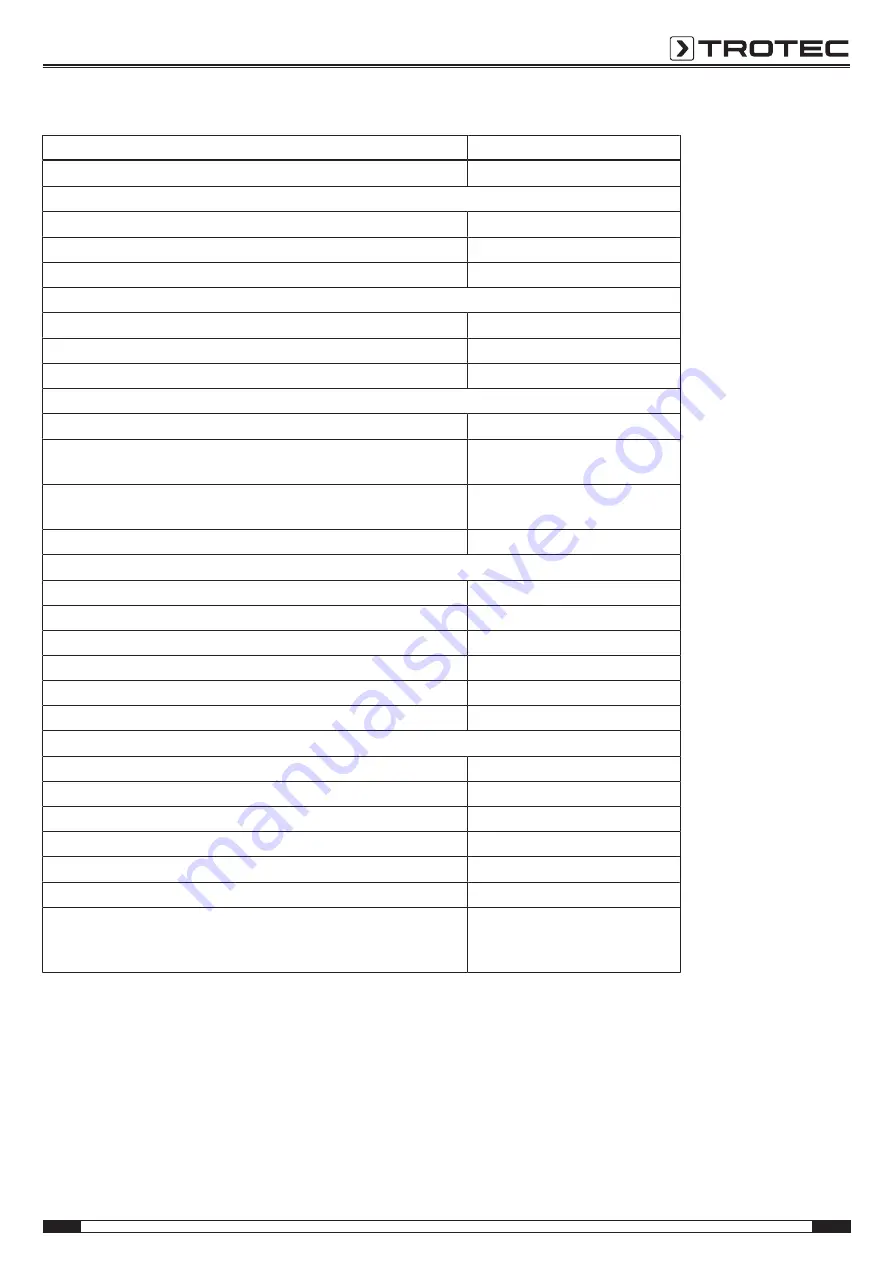
background image

EN

15

fan heater TFC 21 E

Information requirements for electrical local space heaters

Parameter

Value / item

Model

TFC 21 E

Heat output

Nominal heat output P

nom

2.0 kW

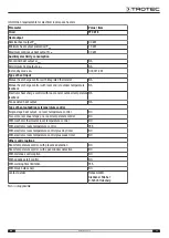
Minimum heat output (indicative) P

min

1.3 kW

Maximum continuous heat output P

max,c

2.0 kW

Auxiliary electricity consumption

At nominal heat output el

max

NA

At minimum heat output el

min

NA

In standby mode el

sb

0.00021 kW

Type of heat input

Manual heat charge control, with integrated thermostat

NA

Manual heat charge control with room and/or outdoor temperature
feedback

NA

Electronic heat charge control with room and/or outdoor temperature
feedback

NA

Fan assisted heat output

NA

Type of heat output/room temperature control

Single-stage heat output, no room temperature control

NO

Two or more manual stages, no room temperature control

NO

With mechanic thermostat room temperature control

NO

With electronic room temperature control

YES

With electronic room temperature control plus day timer

NO

With electronic room temperature control plus week timer

NO

Other control options

Room temperature control, with presence detection

NO

Room temperature control, with open window detection

NO

With distance control option

NO

With adaptive start control

NO

With working time limitation

YES

With black bulb sensor

NO

Contact details

Trotec GmbH
Grebbener Straße 7
D-52525 Heinsberg

NA = not applicable

Summary of Contents for TFC 21 E

Page 1: ...TRT BA TFC21E TC220421TTRT02 001 EN TFC 21 E EN OPERATING MANUAL FAN HEATER EN This product is only suitable for well insulated spaces or occasional use ...

Page 2: ...nual in the immediate vicinity of the device or its site of use Warning Read all safety warnings and all instructions Failure to follow the warnings and instructions may result in electric shock fire and or serious injury Save all warnings and instructions for future reference This appliance can be used by children aged from 8 years and above and persons with reduced physical sensory or mental cap...

Page 3: ... device and all combustible materials such as textiles curtains beds and sofas Make sure that the air inlet and outlet are not obstructed Make sure that the suction side is kept free of dirt and loose objects Do not place the device on combustible ground Only use original spare parts for otherwise safe and functional operation cannot be ensured Allow the device to cool down before transport and or...

Page 4: ...st not be covered This symbol located on the device indicates that this label has to be removed before the foot is mounted Residual risks Warning of electrical voltage Work on the electrical components must only be carried out by an authorised specialist company Warning of electrical voltage Before any work on the device remove the mains plug from the mains socket Do not touch the mains plug with ...

Page 5: ...e will be switched off when knocked over or if its upright position is changed in any other manner The tilt protection switches the device off when it is inclined by a few degrees out of its vertical position The tilt protection is also tripped when lifting the device a little e g for transport during operation The device can again be used as usual only a few seconds after placing it back in verti...

Page 6: ...he mains plug while pulling the power cable out of the mains socket Do not use the power cable to drag the device Allow the device to cool down sufficiently Storage Before storing the device proceed as follows Hold onto the mains plug while pulling the power cable out of the mains socket Allow the device to cool down sufficiently When the device is not being used observe the following storage cond...

Page 7: ...rt up chapter and the technical data in the Technical annex chapter Foot assembly 1 Set up the foot 4 2 Remove the sticker at the bottom of the device before mounting the foot 3 Attach the device on the foot 4 from above so that the clips 9 on the device are exactly aligned with the recesses at the foot 4 4 Press the device down to fasten it on the foot 4 4 9 ð The foot 4 clicks into place on the ...

Page 8: ...ge Do not touch the battery compartment with wet or damp hands Note Do not use rechargeable batteries Observe the Technical data for start up 1 Press the upper part on the back of the remote control and pull the battery cover off the remote control 2 Insert a CR 2032 battery into the battery compartment adhering to the correct polarity 3 Slide the battery cover back onto the remote control Connect...

Page 9: ... described in the chapter Assembly and start up you can switch it on 1 Set the mains switch 7 to position I ð The device is now in standby mode 2 Press the On Off button 26 ð An acoustic signal is emitted ð The room temperature set is indicated on the segment display 25 ð The device is switched on Setting the operating mode The device comes with the following operating modes Heating function Frost...

Page 10: ...esired set number of hours until automatic switch on ð The set number of hours flashes in the segment display 25 ð The Timer LED 13 is illuminated 3 Press the Timer button 21 again ð The timer has been programmed and the device will switch on after the predefined time Notes regarding automatic switch on Manually switching the device on disables the automatic switch on function If you select 00 hou...

Page 11: ...the Storage chapter Errors and faults Warning of electrical voltage Tasks which require the device to be opened must only be carried out by authorised specialist companies or by Trotec The device has been checked for proper functioning several times during production If malfunctions occur nonetheless check the device according to the following list The device does not start Check the power connect...

Page 12: ...or at least 3 minutes after maintenance and repair work Only then switch the device back on The device still does not operate correctly after these checks Please contact the customer service If necessary bring the device to an authorised specialist electrical company or to Trotec for repair Maintenance Activities required before starting maintenance Warning of electrical voltage Do not touch the m...

Page 13: ...s soon as it is dirty This is brought to light e g by a reduced capacity see chapter Errors and faults 1 Remove the air filter 6 from the device 6 I II 2 Clean the air filter 6 using a slightly damp soft lint free cloth If the filter is heavily contaminated clean it with warm water mixed with a neutral cleaning agent 3 Allow the air filter 6 to dry completely Do not insert a wet filter into the de...

Page 14: ... 220 240 V 50 60 Hz Power consumption max 2000 kW Type of protection IPX0 Protection class II Plug type CEE 7 17 Cable length 1 6 m Sound pressure level distance of 1 m 50 dB Dimensions with foot depth x width x height 178 x 230 x 660 mm Minimum distance to walls and other objects A top B rear C side D front 100 cm 100 cm 100 cm 100 cm Weight 3 kg Remote control batteries CR 2032 ...

Page 15: ...m and or outdoor temperature feedback NA Fan assisted heat output NA Type of heat output room temperature control Single stage heat output no room temperature control NO Two or more manual stages no room temperature control NO With mechanic thermostat room temperature control NO With electronic room temperature control YES With electronic room temperature control plus day timer NO With electronic ...

Page 16: ...d for your country The separate collection of waste electrical and electronic equipment aims to enable the re use recycling and other forms of recovery of waste equipment as well as to prevent negative effects for the environment and human health caused by the disposal of hazardous substances potentially contained in the equipment In the European Union batteries and accumulators must not be treate...

Page 17: ...Trotec GmbH Grebbener Str 7 D 52525 Heinsberg 49 2452 962 400 49 2452 962 200 info trotec com www trotec com ...

Reviews: