6
EN
fan heater TFC 21 E
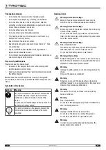
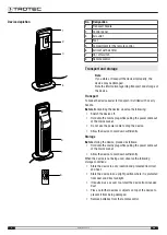
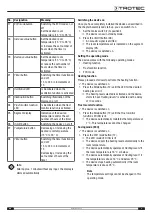
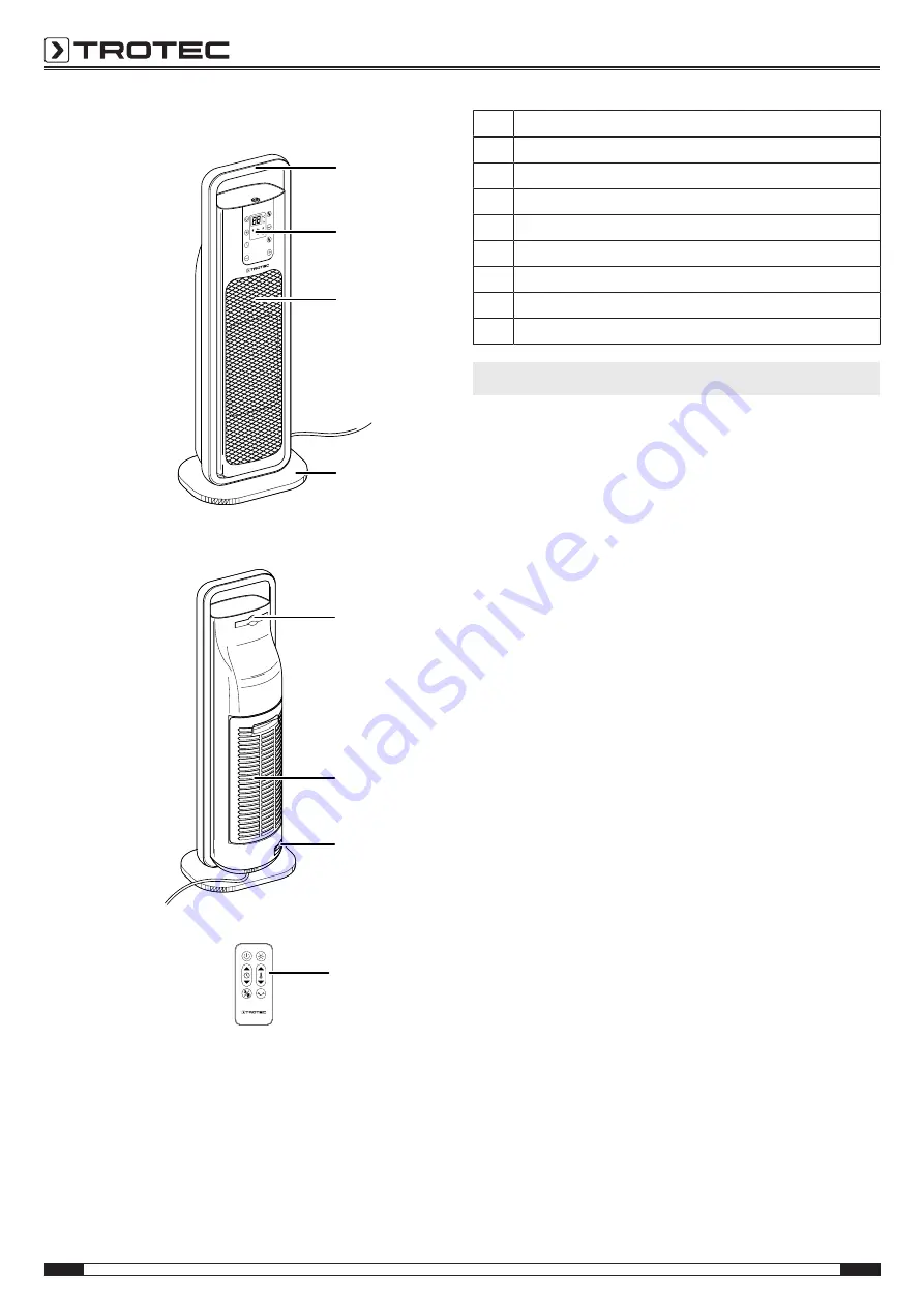
Device depiction
1
2
3
4
5
6
7
8
No.
Designation
1
Transport handle
2
Control panel
3
Air outlet
4
Foot
5
Compartment for the remote control
6
Air inlet with air filter
7
On / off switch
8
Remote control
Transport and storage
Note
If you store or transport the device improperly, the
device may be damaged.
Note the information regarding transport and storage of
the device.
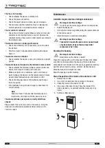
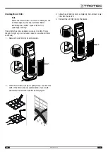
Transport
To make the device easier to transport, it is fitted with a carry
handle.
Before
transporting the device, observe the following:
•
Switch the device off.
•
Hold onto the mains plug while pulling the power cable out
of the mains socket.
•
Do not use the power cable to drag the device.
•
Allow the device to cool down sufficiently.
Storage
Before
storing the device, proceed as follows:
•
Hold onto the mains plug while pulling the power cable out
of the mains socket.
•
Allow the device to cool down sufficiently.
When the device is not being used, observe the following
storage conditions:
•
Store the device in a dry location and protected from frost
and heat.
•
Store the device in an upright position where it is protected
from dust and direct sunlight.
•
If required, use a cover to protect the device from invasive
dust.
•
Place no further devices or objects on top of the device to
prevent it from being damaged.
•
Remove batteries from the remote control.


