5.5 Supporting construction – solid ceiling slabs
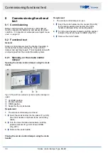
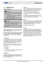
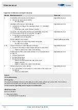
5.5.1 Mortar-based installation
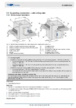
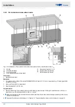
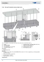
Fig. 11: Mortar-based installation in solid ceiling slabs, classification index: h
ow
①
EK-EU, actuator encasing above ceiling slab
②
EK-EU, actuator encasing underneath ceiling slab
③
Actuator encasing
④
Solid ceiling slab
⑤
Mortar
⑥
Angle section (by others)
Ⓐ
Installation side
Ⓑ
Operating side
B × H
Nominal size (damper cross section, inside)
b × h
Installation opening
s
Perimeter gap
≤
70 mm
D
Ceilig thickness
≥
150 mm
Casing lengths
–
Installation of actuator encasing above ceiling slab (Fig. 11/1) with casing length L = 600 mm or 800 mm
–
For ceiling thickness = 150 mm and if no fire-resistant smoke extract duct is to be connected below the
ceiling: L = 600 mm.
–
For ceiling thickness > 150 mm or if a fire-resistant smoke extract duct is to be connected below the
ceiling: L = 800 mm.
–
Installation of actuator casing under ceiling slab (Fig. 11/2) with casing length L = 800 mm
–
For ceiling thickness = 150 mm: casing length L = 800 mm
The connection of a fire-resistant smoke extract duct above the ceiling is only possible with an angle sec-
tion thickness of d = 35 mm.
Installation alternative outside the ceiling slab
To prevent sleeve joints between the damper and the duct in the ceiling slab, the damper can alternatively be
placed outside the ceiling slab in the flow of the approved smoke extract duct,
Personnel:
Specialist personnel
Materials:
Mortar
‘Acceptable mortars for mortar-based installation’ on page 12
For angle section: strips of fire-rated PROMATECT®-LS board d = 35 mm or equivalent e.g. Promat type AD40
or L500 d = 40 mm
Glue e.g. Promat K84 or equivalent
Dry wall screws 4
×
70 mm for angle section d = 35 mm
Dry wall screws 4
×
80 mm for angle section d = 40 mm
Requirements:
Installation
Supporting construction – solid ceiling slabs > Mortar-based installation
Smoke control damper Type EK-EU
17


