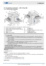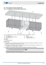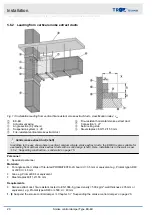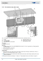
5.3.3 Adjoined damper installation
Side by side
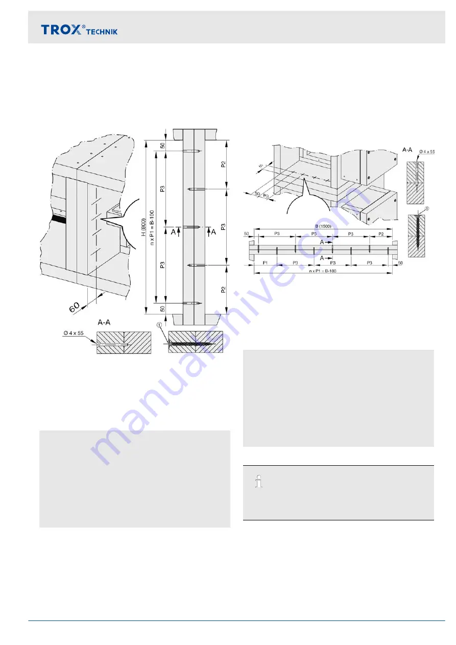
The casings are screwed in to the vertical H parts
(opposite the actuator encasing) on both sides of the
damper (installation and operating side).
Fig. 6: EK-EU side by side
1
m
×
dry wall screw 6
×
80 mm (by others)
n
H - 100 / 200 (round up if necessary)
P1 H - 100 / n (
≤
200 mm)
P2 P1 + 50
P3 P1
×
2
m n + 1 (number of screws)
Calculation example:
H = 800 mm
n = 800 - 100 / 200 = 3.5 -> 4
P1 = 800 - 100 / 4 = 175 mm
P2 = 175 + 50 = 225
P3 = 175
×
2 = 350
m = 4 + 1 = 5
On top of each other
The casings are screwed in to the horizontal B parts on
both sides of the damper (installation and operating
side.
Insert screws both from the top damper and from the
bottom damper; do not insert all screws in one line, but
pre-drill in an offset pattern.
Fig. 7: EK-EU on top of each other
1
m
×
dry wall screw 6
×
80 mm (by others)
n
B- 100 / 200 (round up if necessary)
P1 B - 100 / n (
≤
200 mm)
P2 P1 + 50
P3 P1
×
2
m n + 1 (number of screws)
Calculation example:
B = 1500 mm
n = 1500 - 100 / 200 = 7
P1 = 1500 - 100 / 7 = 200 mm
P2 = 200 + 50 = 250
P3 = 200
×
2 = 400
m = 7 + 1 = 8
Technical advice
If you need more than two dampers sidy by side or
on top of each other, consult with TROX to determine
if this is technically feasible.
Installation
General installation information > Adjoined damper installation
Smoke control damper Type EK-EU
13


