4-way arrangement with common duct
Direct assembly of 4 fire dampers and connection/
sealing using blanking plates provided by others.
The blanking plates (galvanised steel, min. 1 mm,
approx. 60 mm wide, L = 2
×
W / H + 60 mm) are
positioned on a duct seal and screwed on with self-
tapping screws spaced approx. 150 mm apart.
Mineral wool as filling material
Unless otherwise stated in the installation details, min-
eral wool with a gross density of ≥ 80 kg/m³ and a
melting point of ≥ 1000 °C must be used.
Fire-resistant cladding
When you use installation kit WE, the following mate-
rials are acceptable for the cladding of fire dampers and
ducts:
Promatect® LS35
Promatect® L500
Promatect® AD40
Installation with installation kit ES
Casing length L = 500 mm
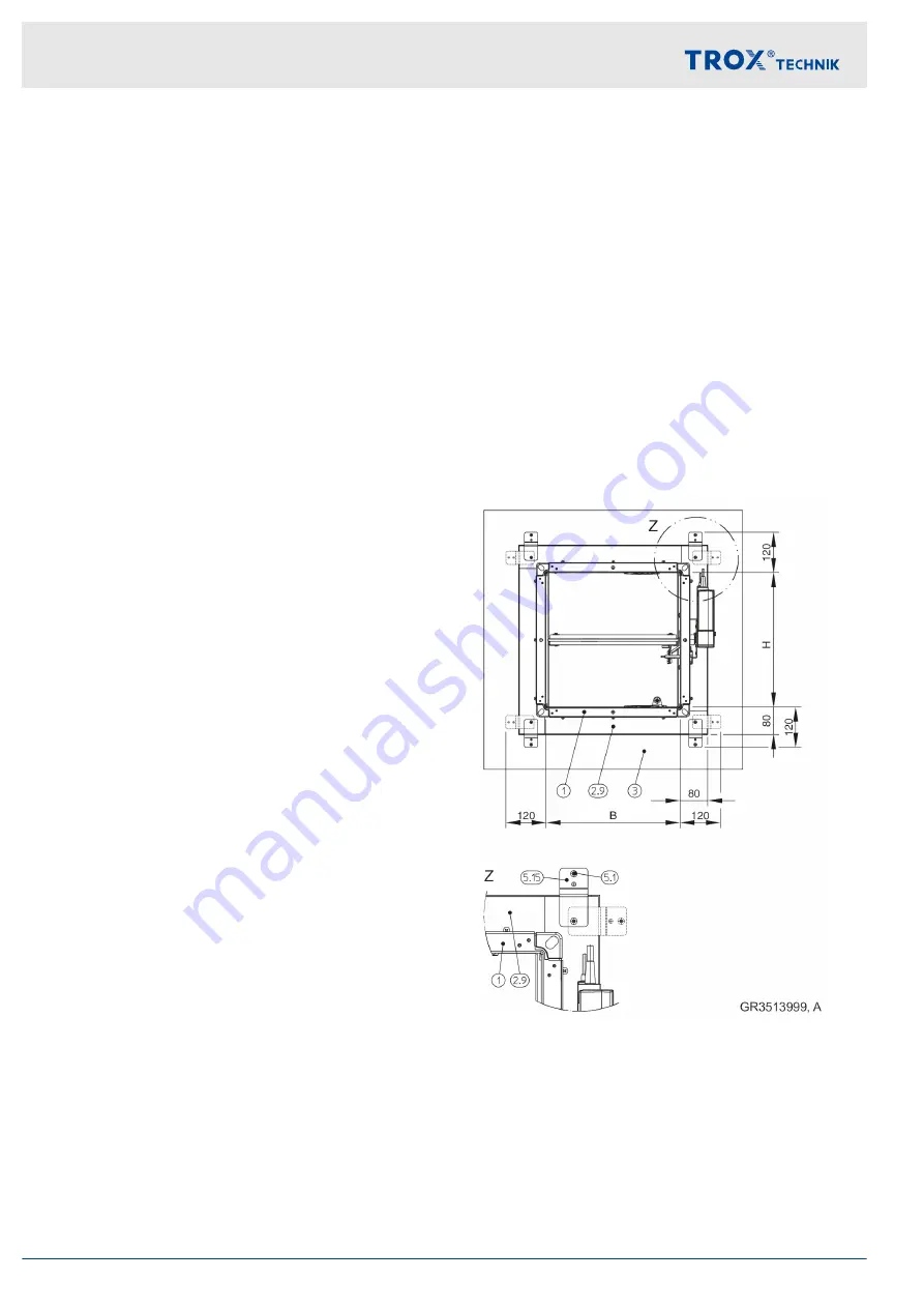
The installation kit must be mounted on the fire
damper by others.
Enough clear space is required for installation of the
installation kit.
The installation kit ES is fastened with dry wall
screws
Æ
5.5 mm and brackets, in which case the
dry wall screws must always engage with the stud
frame. The dry wall screws must be long enough so
that the damper can be firmly fastened. The holes of
the fixing points on the B side are made in the fac-
tory.
For installation near the floor or ceiling, professio-
nally shorten the installation kit on one side. Then
use the brackets that were previously on sides B
and fix them in the upper parts of sides H (see
installation details). The holes must be pre-drilled to
Æ
4 mm.
Fig. 16: Installation kit – free space (with normal installa-
tion)
1
FKA2-EU
2.9
Installation kit ES
3
Wall
5.1
Dry wall screw, to be provided by others
5.15 Bracket
Installation
General installation information
Fire damper Type FKA2-EU
32

