Fire dampers
Correct use
FKR-EU
1
Design information
– Approved only for use in ventilation
and air conditioning systems
– If the fire damper is installed in solid walls
and ceiling slabs, timber stud walls as well
as shaft walls with a lower fire resistance class
than that of the fire damper, the fire resistance
class of the wall or ceiling slab applies
also to the FKR- EU
– Loads imposed on the casing may impair the
function of the fire damper. Install and connect
the damper in such a way that no loads
will be imposed on the installed damper.
– For particular applications it is recommended
that flexible connectors are used to connect
rigid ducting to the unit.
– Inspection accesses are provided
for maintenance and cleaning work
– For further information relevant to design,
in particular information on installation
situations, please refer to the operating
and installation manual.
K4 – 1.1 – 8
03/2017 – DE/en
Incorrect use
Never use the fire damper
– without specially approved attachments
in areas with potentially explosive atmospheres
– as a smoke control damper
– outdoors without sufficient protection
against the effects of weather
– in atmospheres where chemical reactions,
whether planned or unplanned, may cause
damage to the fire damper or lead to corrosion
If this fire damper is used in Germany:
– Do not use it as an air transfer damper.
– Do not use it in extract air systems
in commercial kitchens.
– A class of performance up to EI 120
(v
e
, h
o
, i ↔ o) S can only be achieved
with ducts connected on both ends,
or with a duct on one end and a cover grille
on the other end.
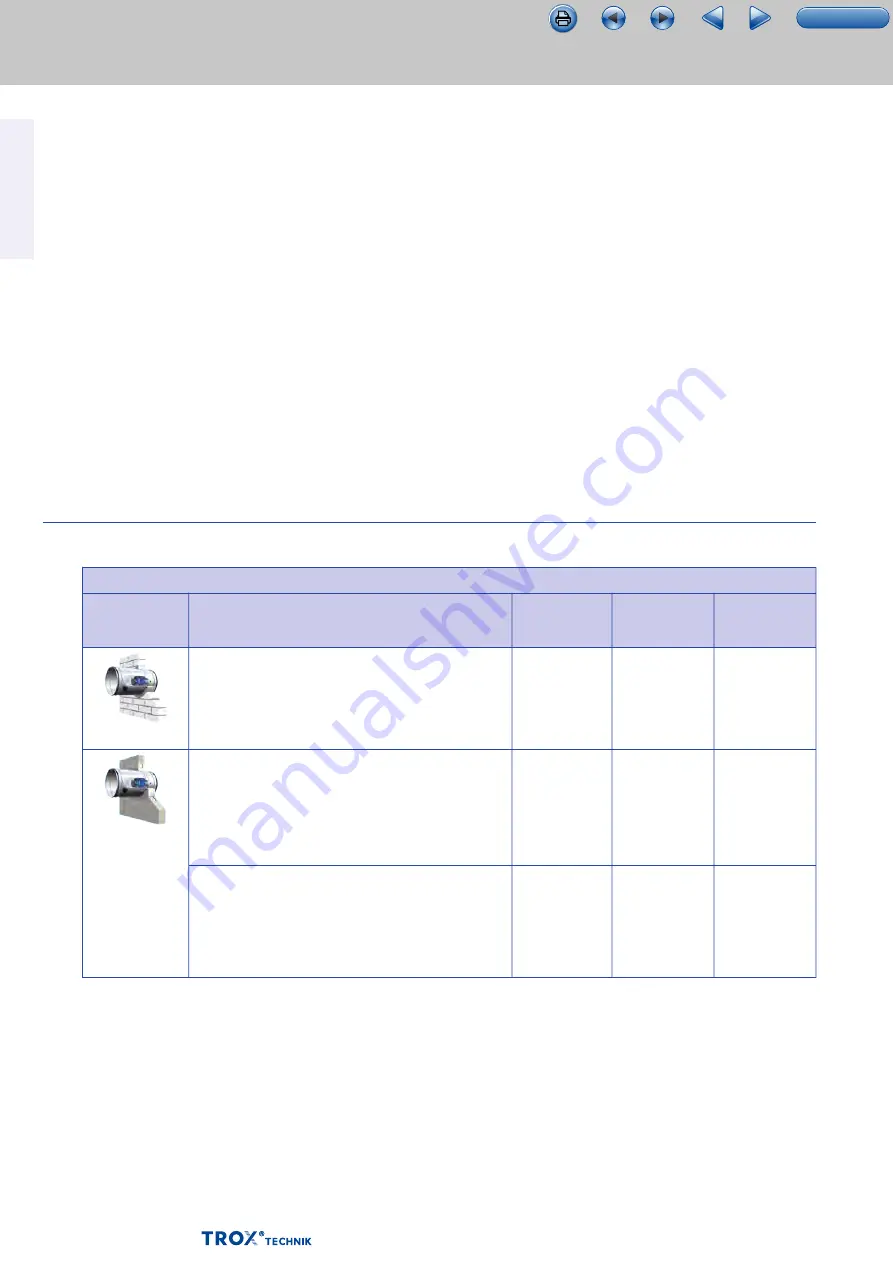
Essential characteristic: fire resistance ― size [mm]: Ø 315 to Ø 800
Supporting
construction
Solid wall
Lightweight
partition wall
Construction
• d ≥ 100 mm
• Distance to load-bearing structural elements ≥ 40 mm
• Distance between casings ≥ 40 mm
•
Metal support structure or steel support structure
•
Gypsum bonded or cement bonded panel materials, fibre-
reinforced gypsum or fire rated calcium silicate boards
• d ≥ 98 mm
•
With or without mineral wool
• Distance to load-bearing structural elements ≥ 40 mm
•
Installation kit TQ
•
Metal support structure or steel support structure
•
Gypsum bonded or cement bonded panel materials, fibre-
reinforced gypsum or fire rated calcium silicate boards
• d ≥ 98 mm
•
With or without mineral wool
• Distance to load-bearing structural elements ≥ 40 mm
• Distance between casings ≥ 40 mm
Installation
location
in the wall
in the wall
in the wall
Installation type
Mortar-based
installation
Dry mortarless
installation
Mortar-based
installation
EI 120 (v
e
i↔o) S
EI 90 (v
e
i↔o) S
EI 90 (v
e
i↔o) S
Class of
performance
(EI TT)
TOC


