C
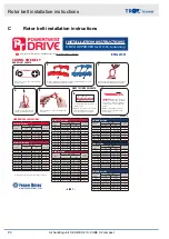
Rotor belt installation instructions
* Belt length is measured open–ended from belt tip to tip
3L/O/Z Section
Hand Tight #
of Links
Belt Length*
# of Links
to Remove
inch
mm
18 – 35
12.6 – 23.8
320 – 604
1
36 – 55
23.9 – 36.7
605 – 932
2
56 – 79
36.8 – 52.0
933 – 1320
3
80 – 101
52.1 – 66.1
1321 – 1678
4
102 – 127
66.2 – 82.7
1679 – 2100
5
128 – 150
82.8 – 97.5
2101 – 2476
6
LINK REMOVAL GUIDELINES
SIZING THE BELT
1
Route the belt so it is “hand–tight” around the
intended pulleys.
Pull tight around
pulleys.
1.
Remove extra
links.
2.
Count and remove
designated # of
extra links.
3.
Make endless.
Turn tabs inside.
4.
Roll on to drive
(belt may seem tight).
5.
INST
ALL GUIDELINES
2
3
With one hand bend belt into an upside down “U”.
With the other hand twist the marked tab 90°.
5
Rotate end tab 90°. Pull belt end through links
to separate.
MAKE TO FINISHED LENGTH
6
Count remaining links or measure belt
length tip to tip.
Note:
For best results, count # of links,
then check final tension with force
deflection gauge after installation.
1 2 3 ...
INSTALLATION INSTRUCTIONS
View the PowerTwist Drive installation video at: www.fennerdrives.com/videos
A/4L/13 Section
Hand Tight #
of Links
Belt Length*
# of Links
to Remove
inch
mm
25 – 34
20.2 – 27.3
513 – 693
1
35 – 58
27.4 – 45.2
694 – 1148
2
59 – 82
45.3 – 63.1
1149 – 1602
3
83 – 105
63.2 – 80.3
1603 – 2039
4
106 – 129
80.4 – 98.2
2040 – 2494
5
130 – 153
98.3 – 116.1
2495 – 2946
6
154 – 176
116.2 – 133.3
2947 – 3385
7
177 – 200
133.4 – 151.2
3386 – 3840
8
201 – 224
151.3 – 169.1
3841 – 4295
9
225 – 247
169.2 – 186.3
4296 – 4732
10
248 – 271
186.4 – 204.2
4733 – 5186
11
272 – 295
204.3 – 222.1
5187 – 5641
12
B/5L/17 Section
Hand Tight #
of Links
Belt Length*
# of Links
to Remove
inch
mm
29 – 34
29.6 – 34.9
751 – 886
1
35 – 58
35.0 – 58.0
887 – 1473
2
59 – 81
58.1 – 80.2
1474 – 2037
3
82 – 105
80.3 – 103.3
2038 – 2623
4
106 – 128
103.4 – 125.4
2624 – 3185
5
129 – 152
125.5 – 148.6
3186 – 3774
6
153 – 175
148.7 – 170.7
3775 – 4335
7
176 – 199
170.8 – 193.8
4336 – 4922
8
200 – 223
193.9 – 217.0
4923 – 5511
9
224 – 246
217.1 – 239.1
5512 – 6073
10
247 – 270
239.2 – 262.3
6074 – 6662
11
271 – 293
262.4 – 284.4
6663 – 7223
12
294 – 317
284.5 – 307.1
7224 – 7800
13
C/22 Section
Hand Tight #
of Links
Belt Length*
# of Links
to Remove
inch
mm
48 – 67
63.4 – 88.3
1610 – 2242
3
68 – 86
88.4 – 113.2
2245 – 2874
4
87 – 105
113.3 – 138.1
2877 – 3506
5
106 – 125
138.2 – 164.3
3509 – 4172
6
126 – 144
164.4 – 189.1
4174 – 4804
7
145 – 164
189.2 – 215.3
4807 – 5470
8
165 – 183
215.4 – 240.2
5472 – 6102
9
184 – 202
240.3 – 265.1
6104 – 6734
10
203 – 222
265.2 – 291.3
6737 – 7400
11
223 – 241
291.4 – 316.2
7402 – 8032
12
242 – 260
316.3 – 341.1
8034 – 8664
13
261 – 280
341.2 – 367.3
8666 – 9329
14
281 – 299
367.4 – 392.2
9332 – 9962
15
3V/SPZ Section
Hand Tight #
of Links
Belt Length*
# of Links
to Remove
inch
mm
<29
<18.0
<457
1
29 – 47
18.1 – 27.7
457 – 705
2
48 – 72
27.8 – 41.2
706 – 1048
3
73 – 96
41.3 – 54.2
1049 – 1378
4
97 – 120
54.3 – 66.9
1379 – 1700
5
121 – 144
67.0 – 80.1
1701 – 2037
6
145 – 168
80.2 – 92.8
2038 – 2359
7
169 – 192
92.9 – 106.1
2360 – 2696
8
193 – 217
106.2 – 119.4
2697 – 3032
9
SPA Section
Hand Tight #
of Links
Belt Length*
# of Links
to Remove
inch
mm
<35
<30.2
<766
1
35 – 49
30.2 – 40.9
766 – 1040
2
50 – 69
41.0 – 56.2
1041 – 1429
3
70 – 86
56.3 – 69.3
1430 – 1761
4
87 – 104
69.4 – 83.1
1762 – 2111
5
105 – 122
83.2 – 96.9
2112 – 2462
6
123 – 139
97.0 – 109.9
2463 – 2793
7
140 – 157
110.0 – 123.7
2794 – 3144
8
158 – 175
123.8 – 137.5
3145 – 3494
9
176 – 193
137.6 – 151.3
3495 – 3845
10
194 – 211
151.4 – 165.2
3846 – 4196
11
5V/SPB Section
Hand Tight #
of Links
Belt Length*
# of Links
to Remove
inch
mm
<47
<51.8
<1316
1
47 – 67
51.8 – 72.0
1316 – 1830
2
68 – 94
72.1 – 99.3
1831 – 2523
3
95 – 126
99.4 – 131.1
2524 – 3332
4
127 – 157
131.2 – 163.0
3333 – 4142
5
158 – 187
163.1 – 193.3
4143 – 4911
6
188 – 220
193.4 – 226.2
4912 – 5746
7
4
Pull link end over tab. For wedge
profiles, repeat with second tab.
With the belt pulled snug, mark the tab that is straight down from the second
overlapping tab (third tab for wedge profiles).
7
IMPORTANT:
Using charts below, find
the range corresponding to the number
found in Step 6. Remove additional #
of links to achieve proper installation
tension.
Note:
For drives with multiple belts,
make sure each belt has matching
number of links.
Pull tight around
pulleys.
1.
Remove extra
links.
2.
Count and remove
designated # of
extra links.
3.
Make endless.
Turn tabs inside.
4.
Roll on to drive
(belt may seem tight).
5.
INST
ALL GUIDELINES
HAND-TIGHT LENGTH
www.fennerdrives.com
– SIDE 1 –
OVER >>
NEW & IMPROVED for NO Re-tensioning
ENGLISH
Rotor belt installation instructions
Air handling unit X-CUBE X2 / X-CUBE X2 compact
80

