1
Operating manual
TROX air terminal units
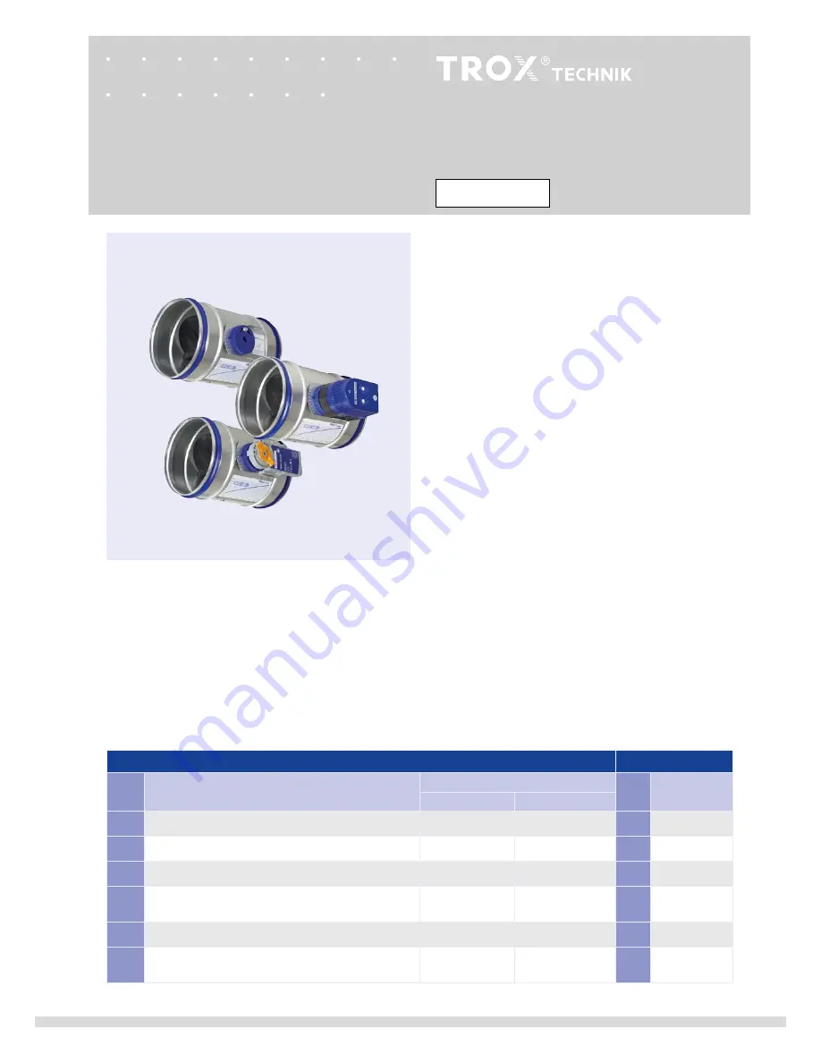
Type VFC volume flow controllers
VFC
VFC series volume flow controllers
Subject to change · All rights reserved © TROX GmbH (10/2018) · Publication no. M/VFC/EN/3
General information ________________________ 2
Correct use __________________________________2
Safety notes __________________________________2
Area of application
_________________________ 2
Operating modes ______________________________2
Product description
________________________ 3
Installation ________________________________ 4
Commissioning and wiring
__________________ 5
Constant volume flow rate operation
_______________5
Variable volume flow rate operation, actuator
with potentiometers
____________________________6
min - max switching wiring
_____________________7
Variable volume flow rate wiring
___________________7
min - max switching operation, actuator
with mechanical stops
__________________________8
min - max switching wiring
_____________________9
min - max switching setting
___________________10
Retrofitting an actuator
_____________________11
Variable volume flow rate expansion set
___________11
min - max switching expansion set
_____________12
1)
Actuators for CAV controllers according to order code
VFC series volume flow controllers
Expansion set
Code
1)
Function
Actuator TROX part no.
Code
TROX
part no.
untill 4/2018
from 5/2018
-
Constant volume flow rate
-
-
-
-
E01
24 V,
min
-
max
switching, potentiometer
M466EP6
A00000038358
E01
NR-VAV-E01
E02
230 VAC, min- max switching, potentiometer
M466EP8
A00000038359
E02
NR-VAV-E02
E03
24 V AC/DC, variable volume flow, potentiometer,
control signal 0 to 10 V DC
M466EP7
A00000038360
E03
NR-VAV-E03
M01
24 V,
min
-
max
switching, mechanical stops
M466EP4
M466EP4
M01
NR-VAV-M01
M02
230 VAC,
min
-
max
switching, mechanical stops
M466EP5
M466EP4
M02
NR-VAV-M02


